SuperSpeed USB Certification: Know Before You Act…
With Intel's introduction of USB 3.0 on the Ivy Bridge platform in 2012, the long-awaited adoption of SuperSpeed technology went into full swing. Microsoft's release of Windows 8 with native support for USB 3.0 host controllers has removed the last remaining hurdles for the 5Gbps connectivity pool. 2013 has been a continuous upward ramp to the market for SuperSpeed products, so USB-IF recently announced that more than 850 products have passed the USB SuperSpeed certification program. The USB-IF Conformance Program has been a cornerstone in the development of this technology, giving designers absolute assurance that their products will interoperate seamlessly with other USB certified systems. USB-IF offers a comprehensive certification program. which is available to its members in regular working groups. In this technical article we are going to explore important processes necessary to achieve USB compliance and time to market.
USB 3.0 Technical Overview
USB aspires to provide seamless connectivity between a host computer and peripheral equipment.
In keeping with the idea of bringing new USB products to market, special design capabilities and test equipment are often required to validate the multiple layers of USB technology. USB 3.0 SuperSpeed is based on a multilayer communications architecture. The major components of this architecture include the physical, link, and protocol layers.
Unlike other serial connections that simply use faster buses to increase performance, USB 3.0 creates a dual-bus architecture, using a separate set of signals that support 5Gbps Superspeed signaling while maintaining the legacy of 480Mbps USB2.0 for safeguard compatibility with previous USB peripherals. The SuperSpeed Physical Layer defines the physical bus connection between host and device. It consists of two differential pairs, one for transmission and the other for reception. USB 3.0 shares similar features to those found in other high-speed serial technologies such as PCI Express and SATA such as 8b/10b encoding, data scrambling, polarity reversal, and wide clock spectrum.
The Link Layer is defined to establish and maintain a reliable connection between host and device. SuperSpeed USB 3.0 introduces some crucial concepts, including: Link Commands (used to ensure successful packet transfer), Link Flow Control, and Management Power. The times, state changes and communication negotiation are defined in the Link Training and Status State Machine (LTSSM). The diagram identifies all of the logical link states that a peripheral must enter when connected to a USB 3.0 compliant host system.
Finally, the USB 3.0 Protocol Layer remains similar to its predecessor. It includes error detection mechanisms, such as CRC fields in all packets. USB 3.0 also adds power management features to the link cap. SuperSpeed hosts do not need to poll a peripheral before initiating a power transition. USB 3.0 allows endpoints to asynchronously notify the host when they have completed their tasks and are ready to enter a low power state.
Preparing for Certification
USB developers should actively consider pre-qualification testing using the same tools as USB-IF's working and control groups and independent test labs.
Selecting these same instruments will reduce unexpected problems that can occur from differences in configuration, signal integrity, or operator error. Investing in test instrumentation may initially seem and be too expensive to test a single OEM USB product.
However, this same USB test instrumentation provides significant value through faster time-to-market, not only in pre-qualification and qualification but also in development, and fewer issues during USB qualification testing. -IF.
It is quite conceivable for OEMs to get the USB logo through the USB-IF working groups or by using one of the many independent labs. Both forms allow to reduce the time to market that USB OEMs need.
USB-IF workgroups are not performed as often as needed by OEMs so going to an independent lab for USB certification is the first option used even if it costs more. OEMs are strongly urged to pre-screen their equipment before entering one of the public USB compliance programs. The introduction of SuperSpeed USB has brought with it additional test equipment mandated by the USB-IF, including a new 5Gbps receiver as well as a new rigorous test of Link Layer requirements. Instrumentation manufacturers such as Agilent, Teledyne LeCRoy, Tektronix, etc. They offer a wide selection of solutions specialized in USB compliance testing.
Of these, only Teledyne LeCroy offers a solution that fully covers the requirements of both the Electrical and Link layers.
USB 3.0 Compliance Test
USB-IF has significantly increased the requirements for USB 3.0 certification. USB 3.0 adds SuperSpeed USB while maintaining full compatibility with USB 2.0 through dual-bus architecture. All equipment is required to meet USB 2.0 pre-certification plus new tests introduced by the SuperSpeed USB specifications, further expanding the certification process. Some of the new requirements are: Receiver Testing; Link Layer Testing; and a new Hub certification test that covers the requirements of Hub Silicon and End Hub devices.
Electrical Coating Test
The SuperSpeed USB 3.0 Electrical Compliance Test specifications require devices to be tested against five Physical Layer tests in addition to USB 2.0 compliance. These tests include:
•TD.1.1 Low Frequency Periodic Signaling (LFPS) TX test
•TD.1.2 Low Frequency Periodic Signaling (LFPS) RX test
•TD.1.3 Transmitted Eye Test
•TD.1.4 Transmitted SSC Profile Test
•TD.1.5 Receiver Jitter Tolerance Test
The LFPS test is performed on both the transmitter and the receiver. It checks that the LFPS transmitter ensures frequency and timing within USB 3.0 specifications while the receiver checks that it can correctly recognize LFPS signaling against voltage swings and duty cycle variations.
Transmitter Test
The transmitter conformance test is aimed at determining whether the Eye Diagram, Random, Deterministic, and Total Jitter meet the USB 3.0 specifications. It also checks the transmitter against the Spread Spectrum Clock (SSC) profile as detailed in the specifications.
USB-IF requires the transmitter to be tested based on the transmitted eye, LFPS timestamp, and transmitted SSC profile. For example TD.1.3 verifies that the transmitter meets the requirements for eye width, random jitter, and deterministic jitter. A bit-error-rate tester that knows the protocol is used to put the DUT (Device Under Test) into compliance mode and is required to send a specific test pattern called CPO (scrambled logical idle). Here an oscilloscope can be used to measure the amplitude of the eye according to the CTLE reference to compare the aperture of the eye diagram.
Receiver Test
The Receiver's jitter tolerance test focuses on measuring the Receiver's ability to receive and interpret incoming data over multiple frequencies. This test is also based on a pattern generator looping the DUT and transmitting specific patterns according to the standard with Ritter added. The DUT sends the received pattern back to the generator and each difference is counted as an error.
The Host and Device transmit data with embedded SKP symbols and by including and removing additional SKP symbols each side can control and validate the clock speed of the opposite side. This forces the test of the receiver because the SKP symbols added and removed in the data stream implies that the data sent by the generator is always different from the data received for bit-error-rate comparison. Therefore the requirement to know the protocol to filter the SKP symbols before comparing the received pattern is critical. The PeRT3 (Protocol Enables Receiver Tester) from Teledyne LeCroy is specifically designed to meet this requirement. These tests significantly increase the complexity associated with USB 3.0 electrical layer compliance. It is highly recommended that developers verify their designs against these requirements before attempting a conformance test at one of the USB-IF sessions or in an independent lab.
Link Layer Test
The critical role of the link layer in establishing and maintaining the integrity of the connection between host and device has extensive testing requirements on the part of the SuperSpeed link layer. Over 130 different link layer standards have been tested with 40 unique tests. Teledyne LeCroy's M3 Voyager platform is one of those approved as a LINK-LVS layer Verification System (Link Verification Systems). Voyager M3 is the only solution based on an integrated parser/builder where all tests are loaded as scripts and users can view and modify the source code for debugging or creating their own tests. Below are two Link Layer test examples.
TD7.5 Link Layer Conformance – Header Packet Framing Robustness: Verifies that the device under test (DUT) will not reject a packet that has a single error symbol in the HPSTART frame. During this test, the traffic generator acting as host or device connects to the DUT. The link initialization sequence is performed and the traffic generator transmits the required Link Management packet with errors in the first symbol of the HPSTART sequence. Passes the test if the link initialization completes successfully. The link is reinitialized and the test is repeated with errors inserted in the second, third, and fourth symbols of the HPSTART sequence respectively. To pass the DUT it must recognize the packet and be in U= for at least 50ms.
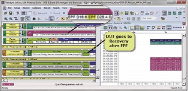
Similarly, TD.7.7- RX Header Packet Retransmission Test validates that the UT rejects packets with a single invalid character in the payload part of the packet header. In this situation the specification requires the DUT to reject the packet by responding with an LBAD bind command. The DUT must remain in U0 while the traffic generator forwards a valid LMP which must be acknowledged by the DUT. This test was expanded to 16 different iterations after it was discovered that some DUTs behaved differently depending on the symbol that was inserted into the header. The image below shows a normal failure condition where the DUT goes into recovery after an EPF (End of packet) symbol appears in the middle of the payload header.
Summary
USB has a well-earned reputation as the easiest and most reliable form of interconnection. The USB-IF compliance program has been the cornerstone for users to have this experience. Designing to ensure flawless interoperability of devices participating in the SuperSpeed logo certification program is an essential part of successfully bringing USB technology to market.
The USB 3.0 certification program represents a substantial testing effort from an OEM design perspective. The examples listed above reflect just some of the complexities OEMs face when beginning USB 3.0 certification.
“Know Before You Act” highlights the importance of careful screening before going to a USB-IF working group for certification.


