In this paper the so-called Bruton gyrator is presented. A type of circuit that at the time found applications in audio due to its ease of replacing inductances with active circuits made up of operational amplifiers, resistors and capacities. In this case, a different application of the rotator is proposed, in which it is configured as a source of direct current whose value is selectable by setting a resistor. Applications of the current source are developed in the polarization of high current LED diodes, Wheatstone bridge sensors and as a battery charger.
Background
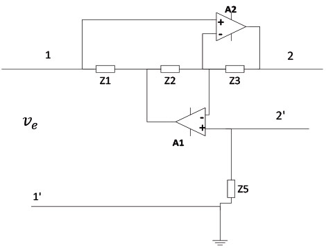
The rotator is a concept that was born in 1948 by Bernard Tellegen to describe those electronic circuits capable of inverting the behavior of an impedance. One of the initially proposed rotary circuits is described by two operational amplifiers and four impedances, as shown in figure 1. This circuit has the property of modifying the frequency behavior of impedance Z4 that is connected between output terminals 2 and 2. '. In particular, the new impedance seen across terminals 1 and 1' is given by the expression:
Zinp=(Z1*Z3*Z5)/(Z2*Z4)
The circuit in figure 2 has a simpler configuration than the previous one, using only one operational amplifier and three impedances, and is called Bruton's gyrator because it was proposed by this engineer [1]. Its input impedance is determined by the expression:
Zinp=(Z3*ZL)/Z2
Note in this case that a negative input impedance is obtained. This fact means that when a voltage generator is connected to its input, it absorbs current for positive values of the voltage and vice versa.
In this way, modifying one of its impedances according to equation (2), such as the Z2 impedance as a capacitor and the other impedances as resistive elements, would give the circuit a negative inductive character, as shown by the input impedance expression. of the resulting circuit:
Zinp=- (R3*RL)/(1/(jwC2))= -jwL
siendo
L=C2∙R3∙RL
Initially, the rotators were used for the synthesis of inductances in RLC passive circuits, converting them in this way into active topologies of only resistors and capacitors.
As miniaturization led to new possibilities, the turntable became an important item finding as many applications during the 60s and 70s as it did in audio. In them it was very important to dispense with uncomfortable inductors (bulky, non-repeatable and not easy to miniaturize) in the design of filters or equalizers.
In this article, the Bruton gyrator is presented working as a source of direct current, an application that is different from the one historically proposed. A current controlled current source and different applications in which the designed current source can be applied are proposed.
Bruton's gyrator as a direct current source
Configuration as a current source begins with the selection of all Bruton rotator impedances as resistive components and the rotator reference or input, by a current reference implemented through the REF200 integrated circuit. This component contains, in addition to an integrated current mirror, two precision current sources that each supply a current of 200 µA. Figure 3 shows the Bruton gyrator configured for operation as a current controlled direct current generator. The output current (i_o) is defined by the expression:
i_o=-(R2/R3)[r_e ]
The value of the output current i_o is easily configurable through the control of resistors R2 and R3, which in turn are the ones that define the gain of the circuit. So, in order to obtain a current range between 25 mA and 1,2 A, two bipolar transistors are incorporated in parallel at the output of the operational amplifier as shown in figure 4, giving the circuit more current capacity.
Due to the low current capacity of the operational amplifier (around 20 mA), two bipolar transistors have been added in parallel in a follower-emitter configuration so that the resulting circuit has the capacity to supply currents of up to 1,2 A. with a maximum gain of 3000. For this purpose, the current reference of the circuit (i_ref) is set at -400 µA, associating in parallel the two 200 µA current references internal to the REF200 integrated circuit. On the other hand, resistor R3 is selected as a fixed component of 5,6 Ω with the capacity to dissipate powers of approximately 8 W, realizing that the maximum current to be supported in this design will be 1,2 A.
The resistance R2 will be of variable order and in the design that is proposed in the range of kΩ. In this way, the level of the output current will be controlled, allowing maximum currents of up to 1,2 A to be reached with gains ranging from 63 to 3000. A symmetrical power supply of ±10 V will be used.
As every design has its limitations, the circuit that is presented sees its operation limited by the maximum output voltage (v_o) that the operational amplifier can reach, this means that it cannot be asked for all the current that is desired by the load. In particular, this voltage must be greater at all times than the sum of the voltage drops between the base-emitter of the transistor, plus the voltage drop across resistor R3, plus the voltage drop across load resistor Rl. Thus the expression must be satisfied:
V_sat,AO≥v_be,sat+I_o∙R3+I_o∙RL
In the case of the current source designed and for a supply voltage of ±10 V, the maximum voltage provided by the operational amplifier used (model OP07) is about 8,4 V.
Under these conditions, correct operation as a current source means considering two possibilities: either increase the load resistance (R_load) and decrease the output current by programming resistance R2, or decrease the load resistance and increase the output current. If equation 5 is satisfied, the system is given a behavior typical of a current source in which it must be independent of the properties of the load to which it supplies its current (resistive load, sensors, leds, etc.).
Table I shows the results achieved with the proposed current source. In it, it can be seen how using a resistive load RL it is possible to achieve current gains of up to 3000 and currents of 1,2 A always under the conditions established by equation (5). As previously mentioned, the gain is set from the value of resistor R2.
The implemented current source finds applications not only to power resistive loads but also other types of loads of interest such as high current LED diodes, resistive sensor bridges or rechargeable batteries. The following shows how the application of the current source in this type of situation has been solved.
Applications
Thermal characterization of high current LED diodes
High current LED diodes are currently a technology of great interest from the applied point of view due to their long life, low consumption and high efficiency. Its constant current supply is of special interest due to the simplicity of this method and its direct voltage drop being established according to its static characteristic. The proposed current source allows polarizing this type of diodes when high levels of current are required. On the other hand, feeding diodes in parallel is very simple, distributing the current equally as long as the loads are similar. The constant current supply of LED diodes associated in series is also possible as long as equation (5) is satisfied, since in this case the load voltage is the sum of the direct drops of the LED diodes.
One of the first experiences has been the development and use of the current source for the temperature characterization of a power LED diode. Figure 5 shows the experimental set-up used. The constant current LED diode has been biased by selecting a set of values (25 mA, 50 mA, 100 mA and 200 mA) by appropriately adjusting the value of resistor R2. For each of them, the LED diode has been subjected to a temperature scan in the interval [-40ºC..+80ºC] using a climatic chamber. Simultaneously, the forward voltage drop across the diode has been measured so that there is a set of experimental measurements that show the thermal drift of the forward voltage VF of the LED diode when it is biased at constant current. The experimental measurements are acquired automatically through a designed acquisition software and the measurement equipment has been controlled through the personal computer through the IEEE488 instrumentation bus.
Knowing said thermal drift will allow us to know the thermal stability of this component and the need or not to carry out a possible thermal compensation in the practical circuits in which it intervenes. Figure 6 graphically shows the thermal evolution of the forward voltage VF of the led diode. It can be inferred that the thermal drift is negative, ranging between -2,27 mV/°C and -3,04 mV/°C. Figure 7 shows the stability of the current source during the time of the thermal characterization test.
Polarization of load cells at constant current
Another of the practical situations in which a current source is applied is in the polarization of sensors. In this work it is proposed to use the current source designed in the power supply of a load cell (four piezoresistors arranged in a Wheatstone bridge configuration). The block diagram of this application is shown in figure 8.
The load cell manufacturer recommends a voltage of 10 V in it, so for an equivalent resistance of 400 Ω a current value of 25 mA must be selected by means of the appropriate adjustment of the resistance R2. The cell conditioning circuit is made up of an integrated instrumentation amplifier (model INA110) and a non-inverting amplifier. The combined action of their gains allows a sensitivity of 1 V/kg in the global circuit. According to the cell model used (full scale of 15 kg), the load/stress characteristic has been experimentally obtained by producing 1kg increments of the input load up to a maximum of 10kg. The designed sensitivity means that the output voltage is between 0 V for a zero load and 10 V for a 10 kg load.
Figure 9 shows how the constant current supply contributes to achieve optimum linearity of the global conditioning circuit. It includes the response of the circuit for increasing and decreasing series of input loads (between 0 and 10 kg). The relative uncertainty has been less than 1,7%.
Tags
led diode applications; current source


