On the way to the All Electric Society, energy storage systems for renewable energy play a vital role. A stable energy supply is only guaranteed if the volatility of the sources can be compensated through sufficiently dimensioned and reliable storage systems.
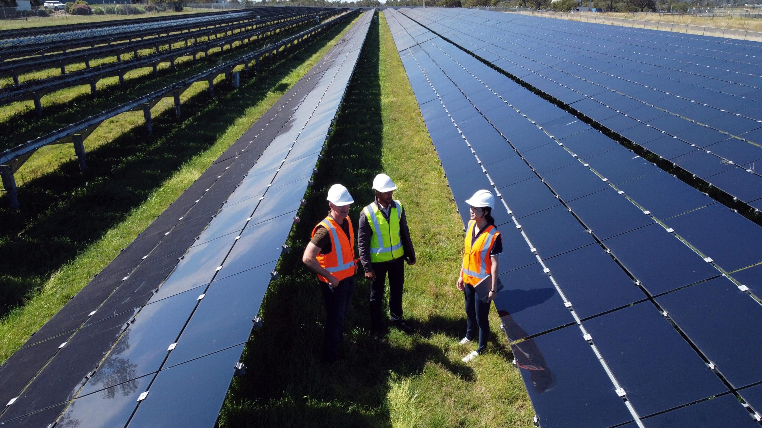
The reliability of these storage systems depends, in particular, on the electrical connection technology used at each and every level. This report describes the design of a storage system for electrical power using a battery system as an example, and focuses primarily on the flow of energy and information between the different levels of this system (primary image).
Typical design of the energy storage system
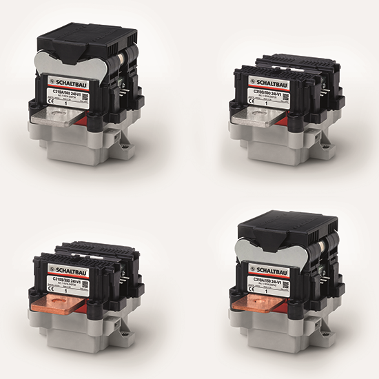
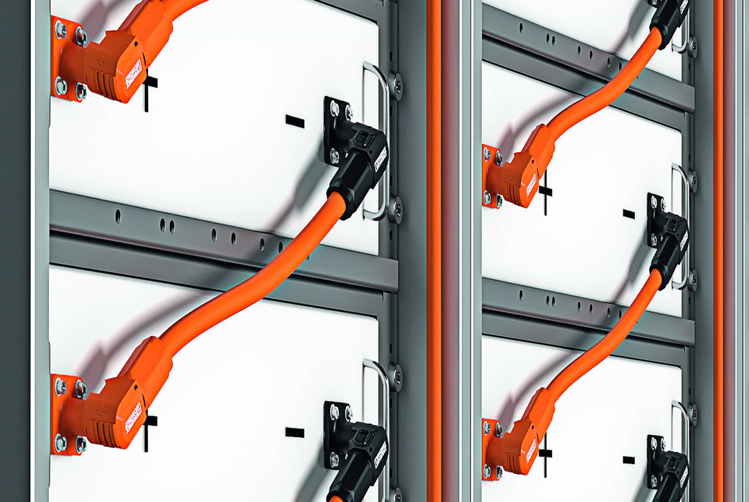
Generally, an electrical energy storage system based on galvanic batteries has a modular design (Image two). With adjustments and only certain restrictions, this principle can be used in both large multi-megawatt-hour storage systems and smaller, ten-kilowatt-hour family storage systems. The basic factor is the battery cell, several of which are connected in parallel or in series to form bundles that increase current and voltage (image three). The first electrical connections are at this very basic level. Here, in most cases, welding technologies are used, that is, permanent connections.
battery module
If a large number of cells are integrated into a housing, it is called a storage module. It is controlled and controlled by an electronic system, known as a BMS module, which is short for Battery Management System.
The electronic system monitors and controls the charging and discharging processes of the battery cells. Here the currents and voltages of the different sets of cells are measured and adjusted so that each and every cell is charged or discharged as evenly as possible. This is called balanced. To enable balancing, it must be possible to monitor each of the sets of individual parallel-connected cells separately. Apart from the 2 connections -positive and negative- for the charge/discharge current, the BMS module also has a high number of connections for the individual cell sets
(see image three).
All information about the status of the battery module - such as the charge status - is processed by a logic system and made available in the form of digital data. Consequently, each BMS module also requires a data interface. Data and power connections are routed from the BMS PCBs to the module housing. In this case, it is customary to use screw connections for the power connections, while for the data interface a plug-in term is mainly used.
Connecting battery modules in a rack
The voltage of an individual battery module is usually in the range of between twenty-four V and ninety-six V. However, the system voltage is usually considerably higher. For this reason, multiple battery packs are connected in series and, in most cases, physically integrated into the appropriate racks (see image two).
For this, flexible cables with circular cable terminals are used between the mentioned screw connections, and the installer must fix each of them. In addition to this, the individual modules are also connected to each other for data communication, which means that at least one data line is directed from each module to the next.
Each rack also includes a supervisor, known as a rack BMS. The rack BMS is developed as an auxiliary slot-in module and is connected to its assigned battery modules via power connections. An auxiliary power interface is used to connect the rack to the higher level system. The rack BMS has multiple data interfaces for exactly the same data traffic. Besides this,
the rack BMS typically has multiple inputs for sensor technology. From the external interfaces of the rack BMS enclosure,
Connections are routed internally to multiple printed circuit boards, where they are screwed, soldered, plugged in, or otherwise electrically connected.
The energy storage system
Depending on the scale, multiple storage racks are integrated to form a higher level system. This also has its supervisor to supervise the loading and unloading processes and to communicate with the outer world. In addition to this, HVAC equipment such as fire sensors and fire extinguishing equipment are included at the system level. This level usually includes containers in which suitable control cabinets carry out the different tasks.
A multitude of different electrical connections as well as the system components and the external connection of the storage system play a vital role here as well. Often the perception is that only energy flows need to be considered, but this is not true. Only the digital connection of the storage system to the grid, to the solar power system or to the wind generator, and to large-scale active loads with feedback option, make the effective use of an energy storage system possible.
Possible failures of the connection technology and their consequences
The number of potential failures in the connection technology is completely manageable. The probability of failures depends primarily on the quality of the components used and the design, the relevance of the technology for the application and the qualifications of the user. An essential requirement to avoid failure in complex electronic systems is a suitable design of the device. This starts with the dimensioning of the connection technology in terms of current intensity and electrical voltage and continues with the consideration of environmental requirements and degrees of protection. These considerations show that corrosion effects can be generated in electrical connections if they are regularly or constantly exposed to humidity. Connectors with IP protection
-from IPX5 to IPX9- are useful in such a case.
The use of circular cable terminals with threaded bolts and nuts, is not surprising that it supposes a source of failures in the power connections.
Due to vibrations, or simply because the bolts are not tightened or do not comply with the directives, greater resistances contact. In the worst case, this causes a fire and, consequently, the total destruction of the system (image four).
Cost optimization
The failure or even the complete destruction of an energy storage system due to failure is the worst possible scenario. Both the owner and the responsible manufacturer, installer or operator suffer notable harm as a result. However, less than perfect designs or system states can also lead to hidden costs that are easy to avoid in most cases.
The external power connectors of a battery pack are used here as an example. Even a properly developed connection and in compliance with the directive can cause losses of more than a thousand kWh per module during its useful life. This increases in direct proportion to the contact resistance. Poor connections that go unidentified can quickly cause losses of multiple megawatt hours or hundreds of dollars per module. At the system level, this translates into economic losses of the order of one hundred euros due to the high number of modules. The initial investment in a higher quality connector pays for itself quickly in such a case.
Likewise, the effort involved in manufacturing the storage system must be taken into account. For example, it may be interesting to replace the soldered connection of a sensor connection on the PCB of the BMS module with a simple to use spring clip for automation reasons. With this approach, when assembling the battery packs, the sensors can be put into an automated process, and the 2 sensor lines are inserted manually and without the need for tools when assembling the module. As a result of the improvement in accessibility, an essential saving of time and, therefore, of costs can be expected.
Summary
The design, quality and proper use of connection technology in energy storage systems are decisive for the cost, reliability and effectiveness of these systems. A compromise that seems inexpensive at first all too often leads to high running costs and system failures. Consequently, it is highly advantageous to always rely on qualified manufacturers when designing the connection technology at each and every level of an energy storage system and rely on their expertise. With its extensive range, Phoenix Contact is able to supply each and every one of the precise connectors for energy storage systems.
Ultimately, the vision of the All Electric Society can only be realized with reliable components.
Energy revolution trend: Ability to recycle energy storage systems
Manufacturers of energy storage systems are increasingly striving to increase the recycling capacity of their systems. Likewise, in such a case, a convenient selection of the connection technology during the design phase of the system can contribute to increasing its useful life and significantly facilitating its recyclability. In such a case, we will only consider one of the many electrical interfaces as an example, and that is the connection of the individual battery cells. If a press-in connection technology were used instead of the soldering process that is common today, it would be considerably simpler to replace any imperfect cells. By disassembling and reusing the removed storage modules, the cells can also be easily removed, examined and, if possible, reused in alternative applications.


