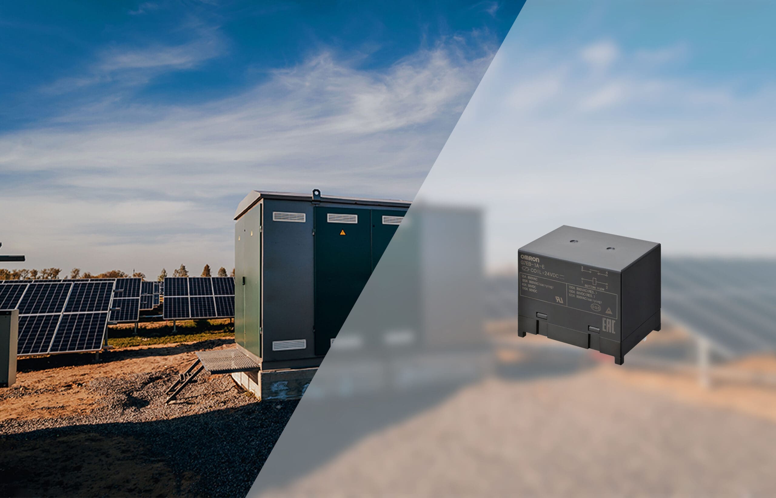
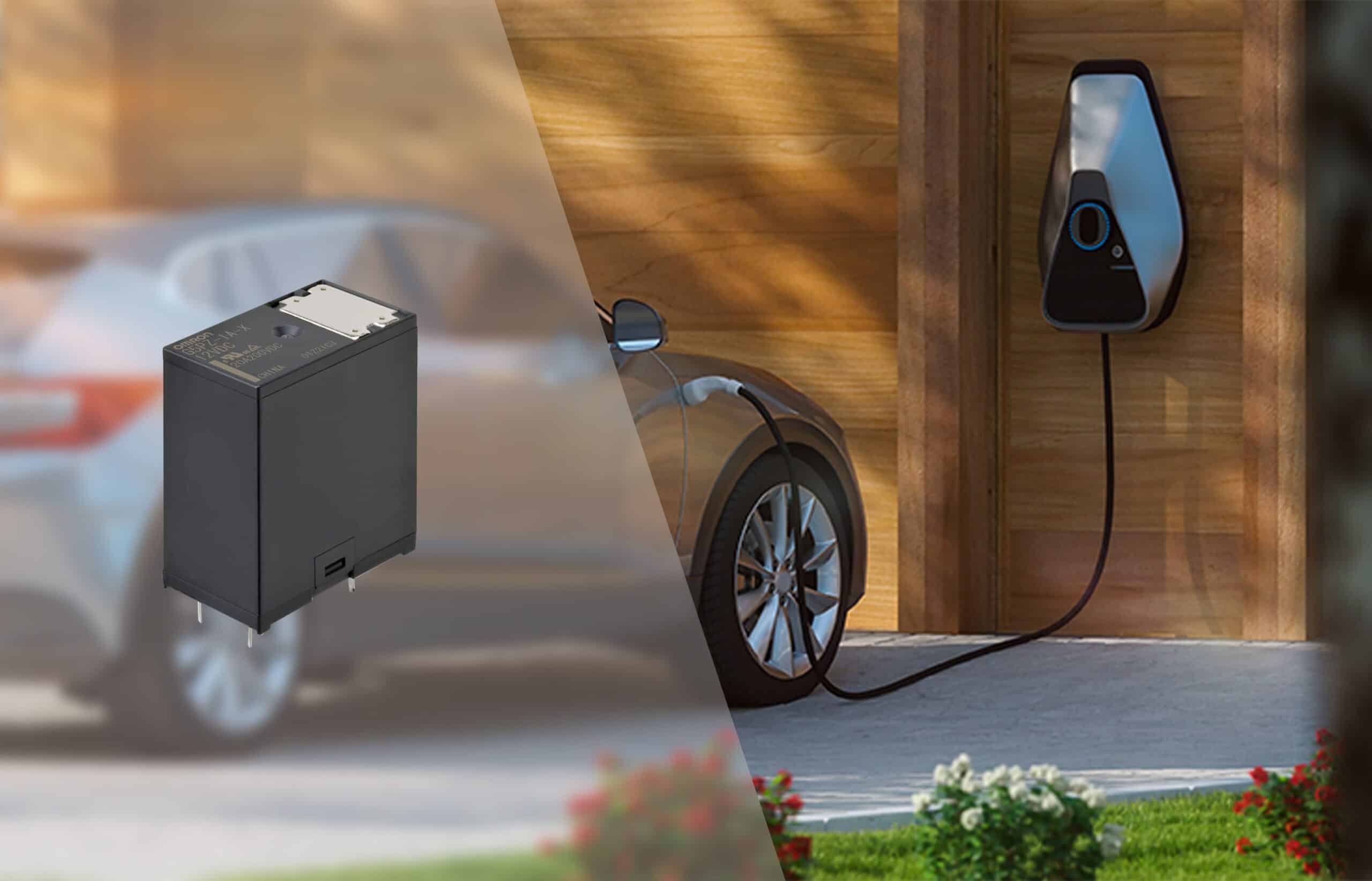
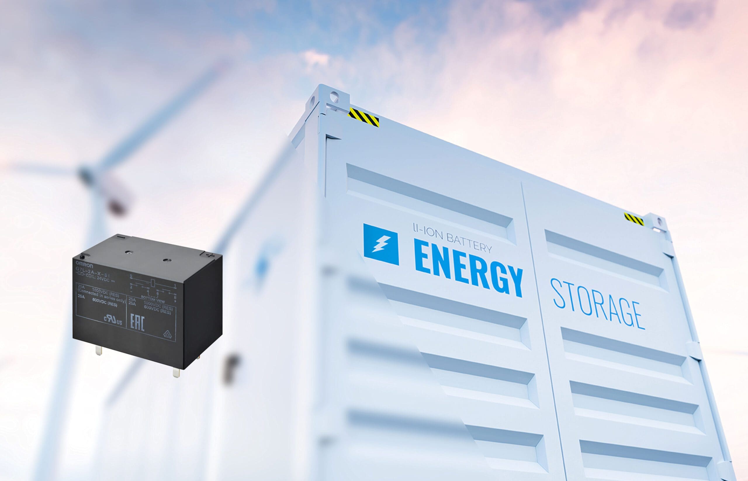
The increasing automation and electrification of our daily lives causes an increase in demand for safe, robust and efficient ways to switch relatively large amounts of power. For example, home solar systems use relays to control the flow of local consumer current through an inverter, store it in the battery, or return it to the utility grid. Electric vehicle (EV) chargers use relays to control the flow of large amounts of energy into car batteries, as well as to protect users by implementing "fail-safe" charging mechanisms and protection systems against leakage current to ground. What may surprise you is how much power is switched by these relays. "Home" car chargers can work with 7 or 22 kW of alternating current (AC), while Tesla's "superchargers" are rated at 250 kW with a high-voltage DC charger. For example, Lotus' Evija electric supercar has an 800V battery pack, which the manufacturer claims is designed to charge up to 800 kW.
This means that Lotus will have to develop a power delivery system – including suitable switching methods, cables, connectors and safety features – that can handle up to 1 kA at 800 VDC. Without a doubt, this will be quite a challenge. The challenge of high current and voltage design with DC This type of electrical engineering comes with several challenges. At the same time that designers try to deliver more electrical power, they also have to increase efficiency by working with higher operating voltages. Higher voltage operation reduces IR losses and I2R heating caused by resistors in the current path. Other ways to increase efficiency include minimizing these resistances and lowering the thermal impedance (or removing heat) from the components so that they cannot increase the temperature and, consequently, the resistance. The drawback of working with higher voltages is that the strength of the electric fields involved increases and this can result in arcing between closely spaced conductors.
Therefore, designers have to take into account two special measurements: creepage, the distance an arc can traverse over a surface; and clearance, the shortest distance an arc can travel through the air. These figures vary and depend on factors such as ambient humidity and air pressure, application standards (for example, sanitary or industrial) and, at least in PCB design, the choice of board, material of the cover and the probability of any surface contamination. In relay design, high voltages can arc when the electric field strength increases if the contact gaps are narrow and the air becomes ionized. This arc can shorten the contacts by increasing their resistance and cause electromagnetic interference (EMI). In the worst case, the arc can cause the relay contacts to weld together, preventing current flow from being cut off without manual intervention. This translates into a serious security problem that must be solved.
The ideal high voltage relay
The challenge for designers wishing to use high-voltage relays is that, to date, many of them have been relatively large, stand-alone components, built to mount as a separate unit with hard-wired connections to a control board. This creates additional costs in terms of supporting components such as plug charges and their terminations, sockets, assemblies, and card connectors, as well as extra processing including manual assembly, inspection, and testing. And every interconnection, from the card to the loads, to the socket or relay connection poses a potential reliability issue. Therefore, the ideal high-voltage relay should be robust and compact enough to offer good power density and be PCB-mountable. The distances (clearances) between its contacts (of very low resistance) have to meet the established technical requirements to suppress the arc and exceed the relevant safety standards.
Creepage distances between relay board connections should be long enough to meet isolation needs while respecting the design allowances of general and application-specific standards. And the relays have to be able to switch high voltages and handle high currents for long periods of time. Safety aspects demand that PCB mount high voltage relays can withstand large inrush and short circuit currents and spikes of more than 10 kV. The relay should also provide strong isolation between the control circuit and the load circuit. Environmental aspects, for their part, require very low contact resistances in order to minimize resistive losses and also require that the currents used to maintain the closed contacts of the normally open relays be low. Finally, a PCB mounted HV relay must also be compact, robust and reliable. A component like the Panasonic HE-V relay meets all of these requirements. Specially designed to manage high power DC loads, it is characterized by 2 Form A contacts, connected in series, and loads of up to 20 A at voltages of 1.000 VDC.
The EV charger design for AC charging stations
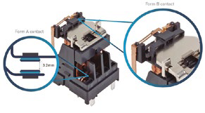
EV chargers also contribute to increasing the demand for power relays. Lower power public and commercial chargers and home chargers supply AC power and rely on the vehicle's on-board electronics to rectify it to DC and charge the batteries. Electric vehicles with power levels around 50 kW use a DC feeder from the charger, since high power rectification is more efficient with the off-board charger. A safe battery charge implies the use of a good number of relays when connecting and isolating the vehicles and the charger, in addition to guaranteeing safety when managing potentially dangerous conditions, such as ground faults or creepage currents. Most of the relays used in such chargers need to control between 16 A at 250 VAC and 32 A at 380 VAC on a three phase system. For safety reasons, the main relay in this circuit would have to be a normally open fail-safe design: should the charger fail, power to the EV is cut off. Relay manufacturers are incorporating new features into their PCB mount products that help designers meet standards and ensure safety while minimizing complexity. For example, the Panasonic HE-S relay has two 2 Form A (single-throw, normally-open) low resistance contacts with the 3,2mm contact gap required to meet the requirements of the IEC 61851-11 standard. Two relays are needed in a three-phase system with one neutral line.
The relay can be supplied with an auxiliary contact switched by a separate actuator and therefore electrically isolated from the main contacts. If these contacts are soldered together, the auxiliary contacts will be able to maintain a 0,5mm gap and thus switch up to 1A at 230VAC. This provides a means for circuit designers to have the features in demand to mitigate contact welding and improve system safety. With the ability to choose materials and make intelligent design decisions to ensure the transmission of large amounts of power at high voltages, it is possible to achieve improvements in the process of functional integration of relays, even in the most challenging circumstances. As a result, designers have more compact, economical, and efficient control circuits to meet the needs of a growing number of applications. And the advantage for customers lies in the appearance of new alternatives to safely use electrical energy and increase well-being and efficiency in our day to day... significant benefits of a rethinking of the relay. If you plan to incorporate PCB mount high voltage relays into your power management systems, you can download a white paper from Panasonic that discusses how to integrate these components into your designs. And, if you wish, you can also contact our technical specialists (in your same language) by clicking the “Ask an Expert” button to solve your design problems in the best possible way.


