The continued growth of the Internet of Things (IoT) and IoT sensors with millions or potentially billions of smart communication devices all connected to the cloud is beginning to spark discussions about the sustainability of this growth.
We can already see a wide variety of IoT sensors available, covering a wide range of applications, such as environmental monitoring sensors, health monitoring sensors or wearables, medical devices and activity trackers, most of which are battery powered. primary.
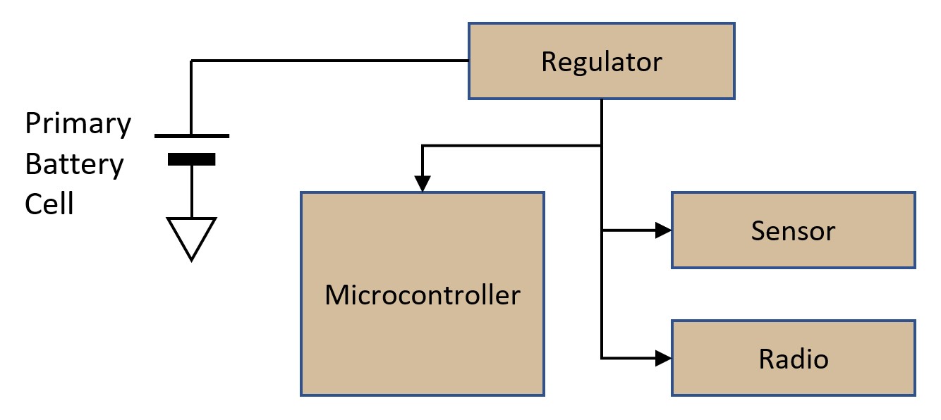
Today, most of these products rely on primary batteries for their operation and questions are being raised about issues related to the use of these batteries. Sustainability and the provenance of the materials used in many of the battery technologies are of great concern. The use of these primary batteries is often also a problem in system deployment, as they typically have a limited lifespan and often need to be replaced during the life of the product, with associated costs. Current IoT sensors that are powered by primary batteries typically use a simple power supply architecture, as shown in Figure 1.
This power architecture is used in most designs as it is very cost effective with either single or multiple batteries with output voltages ranging from 3.0V, 3,6V or up to 6,4V depending on the type of battery technology used. Figure 1 shows that the battery provides the operating voltage used by the microcontroller, sensors, and radio typically found in an IoT sensor. This architecture may not be the most energy efficient, but as mentioned above, it is almost certainly the most cost effective.
In this design, the average current draw of the system is crucial, as it affects not only battery life, but also product life or battery replacement cost. Average current draw and expected product life are important considerations in determining the required battery size. For example, a CR2032 coin cell battery is feasible for IoT devices using a Bluetooth Low Energy (BLE) or ZigBee transmitter (~5mA@3.3V for Tx, 0dBm) for short distance connectivity, but is unlikely to provide viable solution for Radio Solutions that require higher power such as Low Power Transmitters (LPWA) such as LoRaWAN or LTE Cat-NB1 (~100mA@3.3V for Tx, +20dBm) for long distance connectivity.
This type of radio solution requires a larger battery with options like 2 AA batteries. Let's consider the example of a remote environmental sensor to estimate battery life. The sensor will wake up every 15 minutes under the control of a microcontroller, read data from a temperature and humidity sensor, and send the data over a LoRa radio network. In this design, we will use 2x AA (3.0V) batteries as a Energizer E91 as a power source with a capacity of 2500mAh. We will use several Renesas components. The Renesas RL78/G13 ultra-low power microcontroller, a Renesas ISL9122A low-iq buck-boost regulator, a temperature and relative humidity sensor based on MEMS HS300x and for the transmitter element, a Semtech SX1262 LoRaWAN radio chip.
Battery Specification:
| Rated voltage (2x AA) | 3 | V |
| Discharge cut-off voltage | 1.8 | V |
| Capacity (catalog spec) | 2500 | mAh |
| Capacity (valid) | 1500 | mAh |
Energy consumption:
Cycle duration: 15 min.
| Current
[mA] |
Voltage
[IN] |
Duration in 1hr[ms] | Average [uAh] | ||
| Power Consumption | Sensor Access*1 | 2 | 3.3 | 8000 | 4.94 |
| Radio Tx*2 | 85 | 3.3 | 1484 | 36.50 | |
| Radius Rx | 6 | 3.3 | 800 | 1.49 | |
| System Standby*3 | 0.0028 | 3.3 | 3589716 | 0.003 | |
| Total | 42.922 |
Table 1: Example of energy consumption of a remote environmental sensor.
Note 1: Power consumption including microprocessor
Note 2: Power consumption with LoRaWAN configuration SF10/125kHz +20dBm
Note 3: Total power consumption of board components in standby mode (MCU, sensor, radio, PMIC and misc.)
In this example, the battery life is calculated as 1500 [mAh] / 42,922 [mAh] = 34947 hours = 3,99 years. This is a very rough estimate and the shorter battery life is likely due to the regulator's voltage conversion efficiency, which changes as the battery voltage drops as it depletes. However, it shows that, for this example, the product has a useful life of approximately 4 years, at which time we must either replace the battery or dispose of the product. While most IoT sensors With today's reliance on a primary battery as their power source, we have begun to see a number of products being introduced that have adopted the use of energy harvesting sources to increase battery life or eliminate the need for a battery altogether. An example of a typical system design is shown in Figure 2.
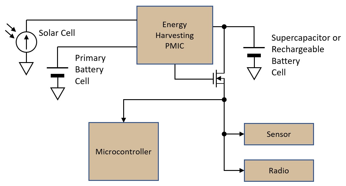
In most systems using an energy harvesting power source, such as solar cells, the input current of the harvesting system is limited, with typical ranges from tens of uA down to 1 mA. A Power Management IC (PMIC) is often used, as can be seen in Figure 2. To supply enough power for the system to function properly, the power must be stored in a rechargeable battery or supercapacitor. The latest secondary battery technologies offer a number of advantages. For example, some types of rechargeable lithium-ion batteries may offer 2,7V, 3,0V, or 3,6V operation. There are pros and cons with these energy storage devices in terms of physical form factor, capacitance range, charging voltage, ESR, leakage current, and cost; therefore, the designer will need to choose an appropriate device that matches the specific requirements of the application.
In the case of using a supercapacitor, the SCM series of AVX or CAP-XX is one of the best options for its low equivalent series resistance (ESR) and low leakage current. For a rechargeable lithium-ion battery, NGK's EnerCera™ ET series (coin cell shape) or EC series (thin flexible shape) is also a good choice for its low ESR and virtually no leakage current.
The use of a PMIC is essential in this power supply architecture, as we need to control the time to start the power supply reliably to supply power to the microcontroller, sensors and radio. The biggest problem with using an energy harvesting power supply in many IoT applications is that the large current drawn by a sensor or radio module could cause the system to fail, since the energy harvesting module can only provide a limited amount of current. . Therefore, PMICs typically include a voltage comparator that allows the application to detect that there is sufficient charge on the energy storage device and manage the time to start the power supply. The capacitance of energy storage devices is important for the sustainability of the system, so it must be carefully calculated to fit the energy balance of the application.
We can consider the same example application again, this time using a small solar cell as a power source. Again we have two sensors, a temperature and humidity sensor and a microcontroller that will wake up every 15 minutes, read the data from the sensors and send the data over a LoRa radio network. This time, as a power source, we use a small Panasonic AM-5610CAR solar panel, with a current output of 300uA. We also use a PCIM from Analog Devices LTC3330 which allows us to support the solar panel and drive an energy storage device, which in this case will be an AVX SCMR1C18 low ESR low leakage 105F supercapacitor. As in the last system architecture example, we will use the RL78 / G13 microcontroller and the HS300x relative humidity/temperature sensor. For the radio, we will again use the Semtech SX1262 LoRaWAN radio chip.
In this design, we also have the option of using a small coin cell primary battery, to provide backup power when power from the solar panel is not possible. However, this is not included in power calculations, and depending on the application and environment, may not be necessary.
Since power generation from an energy harvester is affected by weather or environmental conditions, the use of a primary cell would provide more reliable operation, but is not required. The following table again shows the example of a power balance for the use case of the remote environmental sensor with a duty cycle of 15 min. The energy balance is quite good and there is no need for a primary battery in nominal climatic conditions in the field.
| Current
[mA] |
Voltage
[IN] |
Duration in 1hr[ms] | Average [uAh] | ||
| Power generation | Solar Panel | 0.3 | 3.3 | (9 hours active per day) | 112.50 |
| Power Consumption
|
access sensor | 2 | 3.3 | 8000 | D4.45 |
| Radio Tx | 85 | 3.3 | 1484 | D35.04 | |
| Radius Rx | 6 | 3.3 | 800 | D1.34 | |
| system standby | 0.0028 | 3.3 | 3589716 | D0.003 | |
| Total | 71.68 |
Chart 2: Estimation of the energy balance of an environmental sensor with Energy Harvesting.
As can be seen in Table 2, the power generated by the solar cell is greater than the power consumed by the application, so this is an example of an energy harvesting system that should work reliably and stably. However, it is necessary to consider the capacitance of an energy storage device to keep the system running at night when power is not available from the solar panel. Power will be discharged from an energy storage device, rechargeable battery, or supercapacitor, overnight; therefore its capacitance must be large enough not to over-discharge overnight. Based on the power consumption estimate in the table above, the power storage will require a capacitance greater than the next estimated ballpark number.
C[mF] = E[mJ]-2 / V[V]2 = 4365[mJ]-2 / 3.3[V]2 = 801.6 [mF]
Note that the selection of the energy storage component in the example above is based on this calculation.
Today, companies like Renesas Electronics, with the new RE01 family of microcontrollers, based on the exclusive ultra-low power technology Silicon on Thin Buried oxide, are developing semiconductor devices specifically designed for IoT sensor applications. The RE01 family of microcontrollers integrates many features required in these applications, including an energy harvesting controller designed to both manage power from a low power source as well as from an external energy storage device. These devices facilitate the development of the next generation of IoT sensor applications that can operate reliably while storing energy from the environment around them.
Again, we can create an example of the next generation of IoT sensor design, using energy harvesting to measure temperature and humidity as before with the Panasonic solar cell, AVX supercapacitor, and Semtech Lora radio. This time we will replace the microcontroller with the new RE01-256K microcontroller that has an integrated energy harvesting controller.
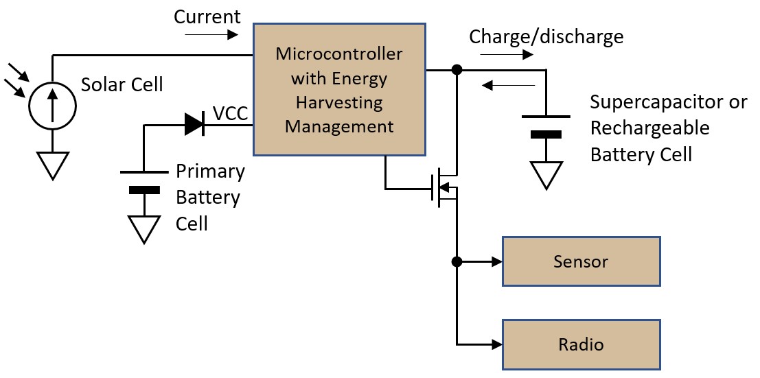
Now the use of the PMIC is not necessary as the energy harvesting management function is integrated in the RE01 microcontroller, therefore the list of material costs is reduced. As shown in Table 2, the energy balance is positive, so this application could work with an optimized solar callout as small as 25mm x 20mm. In this case, if the application can be installed in a well-lit location, we can completely remove the main battery cell from the system design.
Let's take a final example of an energy efficient IoT sensor design using energy harvesting technology, this time using a Thermal Electric Generator (TEG), capable of generating power from a small temperature difference. This is ideal for applications that are installed in environments where there is a temperature difference, such as waste heat in a pipe or motor in a factory, a floating buoy in water, or a door/wall of a building that has contact with air. from outside and inside. The design is especially suitable for locations where batteries would deteriorate faster or difficult environments where access is not easy for battery change.
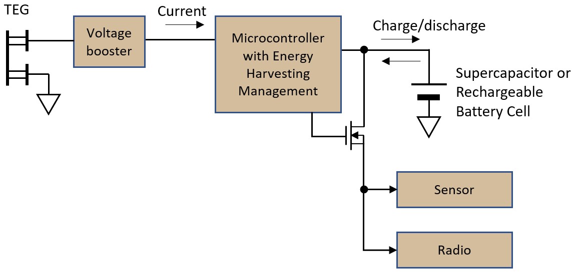
In the past, energy harvesting systems based on TEG elements were not that efficient, typically achieving values of around 30% efficiency in voltage conversion from the TEG output voltage to tens of mV at operating voltage for circuits. electronics, at 1.8V ~ 3.3V. However, recent technological improvements in voltage amplifiers have raised power efficiency up to 80% in the uW power range. According to the Matrix Industries datasheet, a 30mm x 30mm TEG can output 1.4mW at a 20 degree C temperature difference. This is 339,3uA at 3,3V, 80% conversion efficiency .
Figure 5 shows our system layout using the same components as before, but replacing the solar cell with the “Gemini” TEG and “Mercury” voltage booster from Matrix Industries.
Table 3 shows the power demands of the system, this time using a TEG as a power source. The energy balance is good and the system will work semi-permanently, as long as the system is kept in a suitable environment.
| Current
[mA] |
Voltage
[IN] |
Duration in 1hr[ms] | Average [uAh] | ||
| Power generation | TEG | 0.34 | 3.3 | (9 hours active per day) | 127.24 |
| Power Consumption
|
Sensor Access | 2 | 3.3 | 8000 | Δ4.45 |
| Radio Tx | 85 | 3.3 | 1484 | D35.04 | |
| Radius Rx | 6 | 3.3 | 800 | D1.34 | |
| System standby | 0.0028 | 3.3 | 3589716 | D0.003 | |
| Total | 86.41 |
Table 3: Energy balance estimation for a remote sensor powered by a TEG
The latest generation of semiconductor devices, such as the RE01 microcontroller, now enables IoT sensor applications to run reliably from smaller power sources. This, combined with the performance of the latest generation of energy harvesting power sources, such as some of those mentioned here, means that the next generation of sensors will no longer need to rely on batteries. Instead, they can efficiently draw power from the environment around them, potentially reducing or even eliminating the need for batteries.
This allows devices to have a longer life in the field and require less maintenance. More information about the Renesas RE family, and how companies can use energy harvesting elements in their application is available at www.renesas.com/RE.


