Author: Bernd Westoff
The CAN bus has great advantages in terms of cost, flexibility, and robustness that are also highly beneficial for non-automotive applications in many fields. With the extension of the CAN FD bus for higher data rates, the field is even wider. This article covers the fundamentals of CAN and CAN FD buses, also in the aspect of different application implementations using different physical layers or higher layer protocols using CAN as data link layer. The Renesas RA family of microcontrollers is the perfect choice for a platform for CAN bus and CAN FD applications.
Introduction
Due to higher bandwidth requirements in the automotive field, the CAN (Controller Area Networking) specification was extended for flexible data rates, short CAN FD. CAN was defined in the 80's by Bosch and needed an update which is also very beneficial for non-automotive applications.
Advantages
First, let's discuss the great advantages of CAN bus over standard serial communication like RS232 or RS485 due to higher communication speed with error detection, high robustness and lower cost.
cost and flexibility
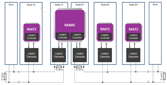
The most important push for the automotive industry was to reduce wiring in the car. Due to twisted pair cabling, it is relatively easy to run the cable, as well as being less heavy and less expensive. Termination resistors are required to run CAN and CAN FD at higher speeds. The flexibility is a great advantage, since it is very easy to expand the system with more nodes.
Error detection and robustness
The CAN and CAN FD buses incorporate highly reliable error checking mechanisms. Bit stuffing and supervision work at layer 1, frame checking, acknowledgment, and cyclic redundancy checking at layer 2 of the OSI model.
Bit stuffing adds an alternate bit after five consecutive high or low bits. If 6 consecutive bits with the same level are detected, there must be something wrong. The bit check is reading every message you are sending. If there is a difference (except in the field of arbitration or recognition) an error is detected. A big advantage is that errors are detected very quickly.
Cyclic redundancy checks are implemented differently on CAN than on CAN FD due to the different data length. Framing errors (sometimes also called format or shape errors) use predefined values that must be the same on the receiving side. Every message must be acknowledged. These three error checking mechanisms largely work at the message level.
In short, the CAN and CAN FD buses are very robust and reliable with several different error checks. No data will be lost during the transmission of a message and message collisions will be avoided. Each node waits for a period of inactivity before sending. In case two messages are sent at the same time, the transmitter detects which message has higher priority and deactivates the lower priority message. Compared to Ethernet, where both messages are stopped and sent later, the message with the highest priority arrives on the CAN bus.
High speed and low latency
The CAN bus supports data rates up to 1 Mbps. With the CAN FD bus the data rate for the Control and Data area can be increased depending on the maximum clock of the CAN FD controller. The rate for the arbitration phase is maintained at a maximum of 1 Mbps. The latency for transmissions on the CAN bus is less than 145us and for CAN FD with 8Msps and 8Byte Data less than 58us.

Short data frames have an advantage in terms of latency. The entire packet is transferred faster, then decoded faster, and therefore the reaction time is much faster. With higher transmission rates on CAN FD, this effect is even greater. Compared to, for example, TCP/IP communication, which is designed for a large amount of data, the packets are relatively large and therefore the latency increases. That means that CAN FD, depending on the amount of data, potentially has shorter reaction times than TCP/IP communication with 10 or 100 Mbit, and shows better throughput in real time, with early error detection.

Limitations
As for the number of nodes, there is theoretically no limit, since each message could be sent to a different node. Virtually every node causes signal reflections on the bus, the transmission quality depends on the CAN transceiver and the physical layer implementation. This is also the reason for the limitation in terms of speed when it comes to long distances. Typical values are a maximum of 25 nodes on CAN and a maximum of 8 nodes on CAN FD.
Application examples outside the automotive field
Why use CAN FD outside of automotive applications? For the great advantages described above.
CAN and CAN FD are widely used in all industries, for example in:
- building automation
o Elevator and hoist
o Access control, lighting control
or air conditioning
- Auto Parts Market
o Fleet tracking, vehicle tracking
o Logging for predictive maintenance, telematics, insurance, blackbox
o Medical and health equipment
- Industrials
o Industrial drives
o Electrical cabinets
- general market
or gaming machines
- Collaborative
o Between main controller and chained actuators
A great use case for MCUs with two CAN FD controller units in combination with TrustZone and Security is a control unit in building automation that separates the secure from the non-secure parts. A CAN FD controller for the secure side can be used to control critical components such as access controls, ID card readers, etc. The second CAN FD can be used for non-critical control parts in building automation such as lighting, doors inside the building, etc.

Another use case for dual CAN FD units is the Gateway functionality. E.g. for automation systems in large buildings, in large electrical cabinets, communication extension modules, etc. There are many different use cases for MCUs with integrated CAN FD controllers. E.g. for actuators, sensors, control, etc.
CAN FD is well suited for high safety and reliability requirements, for example in robots, elevators and transportation systems, but also in the medical and healthcare field. The reliability requirements of the automotive industry are highly beneficial in these use cases.
Differences between conventional CAN bus and CAN FD
The CAN and CAN FD protocols described in the Bosch specification share the same physical layer. First CAN FD extends the conventional CAN protocol. That means it is backwards compatible with existing CAN 2.0B networks. There are two versions of conventional CAN called CAN 2.0A and CAN 2.0B. It is not possible to use CAN 2.0A (plus earlier versions) and CAN 2.0B / CAN FD on the same bus, as transmission errors may occur. The reason is CAN 29A 2.0-bit message identifiers can't handle, but CAN 2.0B and CAN FD were extended.
CAN 2.0B that does not use 29-bit extended frames is also called passive CAN 2.0B and can be used in CAN 2.0A.
| Version | Send message identifier | Receive message identifier |
| CAN 2.0A | 11 bit | 11 bit |
| CAN 2.0B | 11 bit and 29 bit | 11 bit and 29 bit |
| CAN 2.0B passive | 11 bit (29 bit not used!) | 11 bit (29 bit ignored) |
| CANFD | 11 bit and 29 bit | 11 bit and 29 bit |
Overview of different CAN standards
CAN 2.0A is also called basic or standard CAN. It uses 11-bit message identifiers and is covered in ISO11519.
CAN2.0B is called full CAN. It used 11 and/or 29 bit message identifiers and is covered in ISO11898 (-1: data link layer, -2: physical layer for high-speed CAN, -3: physical layer for low-speed fault-tolerant CAN , -2 and -3 are not part of the Bosch specification). CAN FD and CAN2.0B can be used on the same bus.
| Name | Nickname | ISO | Message identifier | Data area | Max. speed | How |
| CAN 1.0, 1.2, 2.0A | Basic or Standard CAN | 11519 | 11 bit (Standard) | 0 to 8 Bytes | Doesn't tolerate 29 bit message identifier. CAN 2.0A is supporting also 1.0 and 1.2 | |
| CAN 2.0B | Full CAN or extended CAN | 11898-1 | 11 bit (Standard) and 29 bit (Extended) | 0 to 8 Bytes | 1Mbit / s | Supports both, Standard and Extended frames can exist on the same bus. Standard frame has the highest priority. |
| CANFD | CAN Flexible Data Rate | 11898-1: 2015 | 11 bit (Standard) and 29 bit (Extended) | 0 to 64 Bytes | 1Mbit/s and 8Mbit/s for data and control area | different data length, switching to a faster bit rate after the arbitration |
The CAN message structure with all extensions is the same. The difference is in the larger data area in CAN FD with a maximum of 64 bytes compared to a maximum of 8 bytes in CAN. And in the highest transmission rate for CAN FD Control and Data area
CAN and CAN FD as the basis for different variants
The physical and data link layers (layer 1 and layer 2 in the OSI model) are defined in the CAN/CAN FD standard. They are the basis for industry variants in higher layers, but also for different physical layer implementations.
Different physical layer implementations
The most common physical layer implementation is the use of standard transceivers with 5 V over twisted pair cable. There are other physical layer variants that use a single-wire CAN transceiver or low-speed, low-power physical layer variants.
Higher level protocols using CAN or CAN FD
CAN or CAN FD form the data link layer for higher layer protocols used in the following industry-specific cases.
DeviceNet
"DeviceNet" managed by ODVA is an application layer protocol that uses CAN on both the data link and the physical layer. The reason for this is that CAN is superior to the traditional RS485 used. The main applications are in factory automation.
CANOpen
In the “CANopen” standard, Full CAN forms the data link layer, for “CANopen FD” it is CAN FD, both managed by CiA with different flavors:
- “CANopen” (CiA 301) based on classic CAN for integrated general control in real time
- “CANopen FD” (CiA 1301) based on CAN FD and CAN XL for integrated real-time control with advanced functions
- J1939 profile for classic CAN and CAN FD for commercial road vehicles
- Classic CAN based Isobus profile for agricultural and forestry machines based on J1939
- Classic CAN-based NMEA2000 profile for maritime applications based on J1939
(Source CAN in Automation (CiA): Standardized Upper Layer Protocols (can-cia.org))
TTTCAN
Time Triggered CAN is adding a time triggered message transmission to the existing CAN protocol. This allows messages to be transmitted at defined time intervals. With this, several masters can transmit messages with the CAN arbitration principal in the time slot assigned to each master. This is further improving real-time behavior.
In short, the CAN bus can be used on different physical layers. The most common is 5V twisted pair wiring with differential signals implemented with standard transceivers in combination with an MCU with integrated IP CAN controller. The other variants are protocols at higher levels using the physical and/or data link layer of CAN. These are e.g. CANopen or DeviceNet
Implementation with the RENESAS RA family
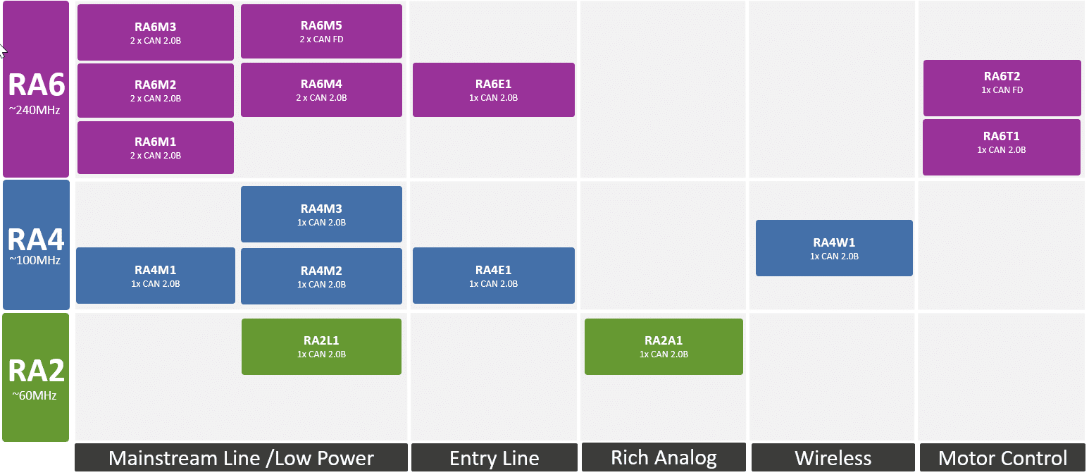
There is a long list of RA family microcontrollers that integrate a CAN 2.0B controller, including the RA2 series with RA2L1, RA2A1, the RA4 series with RA4M1, RA4M2, RA4M3, RA4E1, RA4W1 groups, the RA6 series with RA6T1 and RA6E1 groups. .
Additionally, the RA6 Series comes with two CAN 2.0B controllers in the RA6M1, RA6M2, RA6M3 and RA6M4 groups.
The RA6T2 group integrates a CAN FD or CAN 2.0B controller and the RA6M5 group two CAN FD or CAN2.0B controllers.
All future RA devices will support CAN and CAN FD instead of just CAN
Renesas RA MCUs are based on Arm Cortex-M cores, with TrustZone and Secure Crypto Engine for high security requirements in connected applications. The Flexible Software Package (FSP) offers highly efficient CAN and CAN FD controllers that can be easily configured with configuration tools. It is very easy to integrate higher level protocols using CAN or CAN FD with the common API.
The IP used in the RA MCUs that integrate CAN FD is fully compliant with CAN-FD ISO 11898-1 (2015). The RA6T2 with one CAN FD controller supports up to 5 Mbit/s for the data phase, the RA6M5 with two CAN FD controllers supports up to 8 Mbit/s on each channel.
The RA6M5 can be perfectly used as a host with rich connectivity in an access panel, communication module or gateway to combine CAN2.0B ↔ CAN2.0B, CAN2.0B ↔ CAN FD or CAN FD ↔ CAN FD .
The RA6T2 is ideal as an actuator with extensive timer functionality to control motors in industrial drive applications.
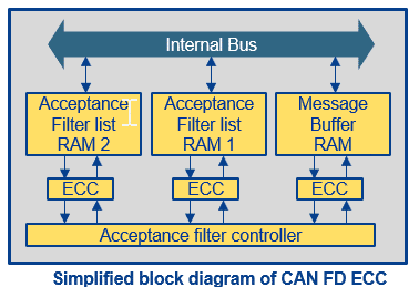
The RA implementation includes two receive FIFO buffers and one common FIFO configurable as a receive or transmit FIFO per unit. FIFO RAM is ECC RAM with error correcting code for higher reliability in security applications.
The RA family of microcontrollers is the perfect choice for a platform for CAN and CAN FD applications.
The Renesas RA family now has more than 201 parts ranging from 48 MHz to 240 MHz. The RA family MCUs offer industry-leading power consumption specifications, a wide range of communication options, and the best options for best-in-class security, including Arm TrustZone® technology. All RA devices are supported by the Renesas Flexible Software Program (FSP) that includes highly efficient drivers and middleware to ease communications and security implementation. The FSP GUI simplifies and speeds up the development process. It allows flexible use of legacy code, as well as easy compatibility and scalability with other devices in the RA family. Designers using FSP also have access to the extensive Arm ecosystem, which offers a wide range of tools that help speed time to market, as well as Renesas' extensive partner network.


