In a multitude of applications, from the simplest mobile phone chargers to power grid inverters operating at hundreds of kW, power conversion schemes are used that incorporate an intermediate stage where power is processed into direct current. A “DC-Link” capacitor is suitable at this point to provide a low impedance path to high frequency switching currents and provide energy storage. The input phase can be as simple as a rectifier off an AC line input voltage or a Power Factor Correction (PFC) circuit that generates a constant high voltage current. The DC-link capacitor acts as the output phase filter in the PFC stage, absorbing switching currents to minimize ripple current.
The output stage should be a converter or a switched mode inverter that “cuts off” the excessive frequency current from the DC-Link capacitor. The capacitor also needs to be sized to meet DC-Link ripple voltage specifications and energy storage between utility cycles or when input power is lost. Therefore, it should have a low equivalent series resistance (ESR) and a minimum ratio of capacitance and ripple current.
These specifications must be met with certain parameters of voltage, temperature, power output and switching frequencies to guarantee a long life. For low power AC-DC converters without PFC phase, the minimum capacitance is established by the ripple voltage of the electrical network allowed in the DC-Link. This provides a capacitance value of about 2 μF/W for universal input power. And, for higher power AD-DC converters with PFC, the value is determined by a “hold-up” or “ride-through” time of input power loss and a much lower capacitance value is possible with stored energy. at high voltage. Values of less than 1 μF/W are normal. The capacitance required by hold-up is easily calculated by equating the power needed by the load during that hold-up period; th x Po/η (hold-up time per output power divided by efficiency) with the energy difference in the capacitor between its initial and final voltage, at which the converter stops depending on the specifications (0.5 CV2start – 0.5 CV2finish) This is rearranged to give C = 2 Po th/ η (Vstart2 – Vfinish2) For AC output inverters, hold-up may not be a problem, as only minimal capacitance is needed to achieve low enough impedance at the inverter switching frequency and therefore decrease the ripple voltage.
In practical circuits, the ripple current that the capacitor must handle without dissipation overheating in the ESR often becomes a determining factor. The current can be so high that for a given voltage a minimum capacitor size is required to achieve low ESR, high dissipation and long life. This leads to a capacitance that exceeds the minimum of the ripple line or hold-up calculations. The ripple current waveform is very difficult to predict as it is a combination of line frequency and input and output phase frequencies, and their corresponding harmonics. Waveforms depend on phase topologies and can range from triangular high-rms currents on discontinuous mode PFC phases to squarer currents on bridge inverter and converter phases.
The input and output phase currents “in and out” of the capacitor and not necessarily in phase or at a fixed frequency, complicating matters. Schemes exist where the input and output phases can be synchronized to achieve some ripple current cancellation in the capacitor. From calculation, experiment or simulation, the specifications of the main capacitor can be found, but then there are other considerations to take into account, such as size, cost, lifetime and reliability. A designer will find that there are several types of capacitors available for their application, choosing between aluminum, film and ceramic electrolytics. The selection is not easy and largely depends on the requirements of the project. However, in general, electrolytic models tend to be cheaper and more compact than film and ceramic models for a given combination of voltage and capacitance ratio (CV ratio), but offer lower ripple current. They also have a greater variation in capacitance, ESR, and ripple current with respect to time and temperature, as well as a shorter duration (depending on the applied voltage and temperature). Electrolytic capacitors are only available with a rating of up to 600 VDC compared to the several kV of film variants, thus requiring series connection of various electrolytics with balanced networks in high voltage applications. The initial cost of an electrolytic can be much lower than that of a film with an equivalent CV ratio.
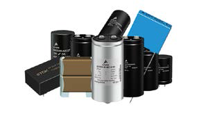
An example could be found in the electrolytic B43544 series and the BMKP 3277 film series from TDK EPCOS. At 470 / 480 µF and 450 V, the ESR of the film type is about sixty times lower, the ripple current is about nine times greater, and the rated life is about four times greater at similar temperatures and frequencies. However, electrolytic is ten times more compact and has one tenth the cost of film. Table 1 provides a summary of the main specifications of the two example capacitors. Perhaps most important is the way in which these specifications vary with the environment and application conditions. Figure 2 shows how the capacitance, loss factor, and lifetime of electrolytic and film capacitors change as a function of temperature. End of life is defined as performance degradation from a certain level, typically a variation greater than 20 percent from initial value, a dissipation factor change of more than 1.3 times initial value, or leakage current above the initial value. specified limit.
If this cannot be tolerated and the component is used at high temperatures, it may need to be replaced many times over the life of the final equipment with associated costs for acquisition, overhaul and downtime. There is a big difference in life between the two types, but over the expected life of an electrolytic capacitor, its inherent reliability is still not that different to ceramic or film versions. TDK EPCOS achieves 10 FITS (failures in 109 operating hours) at 0.5 V and +40 °C for the example with a film capacitor and, although the company does not offer a figure for the electrolytic in its data sheet, these models usually report ratios of 0.5 to 20 FITS. Under voltage stress conditions, film capacitors have the advantage of being self-healing (self-repairing) and withstanding higher overvoltages than electrolytic ones.
Ceramic DC-Link capacitors, such as those in the TDK EPCOS CeraLinkTM range, are only available with capacitances of about 20 μF at 500 V (B58033I5206M001), but by connecting twenty-three units in parallel, values of 460 μF are possible. in 192 cm³ and therefore manage a high ripple current. Each unit is rated to operate at 31.5 A at 100 kHz and +85 °C, so twenty-three elements could, in theory, handle up to 724 A. However, as with other ceramic capacitors, capacitance and ESR values vary. considerably with applied voltage and temperature. To summarize, the choice of the type of capacitor depends to a large extent on the application and the electrolytic models are still a good option in projects sensitive to cost and “little” adverse environments.
When temperatures and ripple current rise, choosing an electrolytic capacitor instead of a film capacitor can provide “false savings” when considering the costs of a short life span and consequent replacement costs and downtime . The TDK EPCOS brand has a wide range of both types of condensers that meet the needs of different adverse conditions and various mounting formats. To facilitate design, Avnet Abacus has developed a new interactive tool that is intended to help you find the best TDK product for inverters and controllers.
This tool also allows you to explore the phases of a driver circuit and identify the most suitable models for each design. Visit http://avnet-abacus.hssites. com/inverters/input-filtering if you want to go directly to the DC-Link section, where you can access datasheets and technical information for the products mentioned in this article. And, if you are interested in more information on input filter circuits or have any questions about a specific inverter design, please contact your local Avnet Abacus specialist.


