Ann-Marie Bayliss, Senior Product Marketing Manager, Murata
Most electronic equipment incorporates some form of DC/DC conversion. The switched mode technique is an efficient solution that allows voltage stepping up and down, as well as providing isolation, with small magnetic components. This article provides an introduction to this technology as well as some commercial solutions.
DC/DC conversion has been a challenge for system and product designers that had its beginnings in the "war of currents" lost by Edison to Westinghouse in the late XNUMXth century. AC distribution with higher power demanded higher and higher voltages to keep currents low and cables to have a reasonable diameter, but this could only be easily achieved with transformers. DC could only be augmented at that time by large generating plants and the rest is history: Westinghouse won and AC distribution became widespread during the XNUMXth century.
The last century also marked the beginning of the era of electronics, which above all needs DC for its components, so it was necessary to convert the distributed AC voltage to DC. But what CC? Circuits can require anything from less than 1V for a processor to several kV for a microwave oven magnetron, and sometimes both. If the rails needed are to be accurate to changes in AC line and load, then active regulation circuitry is also required. Early kits used 50/60Hz transformers to step the AC down to lower voltages that could then be rectified, filtered to DC, and regulated to a lower voltage via a “linear” series transistor. But when load, line, and tolerances are taken into account, the power taken from the AC line is about double the power of the load in the worst case. In addition, the transformer is large, heavy and expensive, so this solution is far from ideal. The DC rail voltage of a system cannot be increased “linearly” in practice.
Switched mode conversion solves the problem
The practical solution for efficient DC conversion, both for stepping down and stepping up the voltage, is the “switched mode” technique. When isolation is not needed, step-down ("buck") or step-up ("boost") converters are used, or variations obtained from them. The reducer (Figure 1, left) “chops up” the input DC at high frequency so that its average is lower, and then filters the resulting waveform with an LC filter. The "chop" transistor is fully on or fully off; in both cases it dissipates little power and the output voltage is fixed by means of the duty cycle of the transistor switching. The boost converter (Figure 1, right) works somewhat differently: by chopping it alternately stores energy in the inductor's magnetic field and then releases it. Power can be released at any chosen voltage greater than the input. Other circuit topologies, such as simple buck-boost and Ćuk, can invert the voltage, while SEPIC, ZETA, and others can generate positive output voltages lower or higher than the input.

Figure 1: Schematics of buck and boost DC/DC converters.
La Figure 2 shows an example of a Murata 78SR series buck converter [1]. This module has an input range of 7,5V to 36V for an output of 3,3V at 0,5A. With its maximum load and a 12V input it achieves an efficiency of 83% dissipating about 0,7W. Its pins are compatible with the well-known 78xx series linear regulators, which would dissipate as much as 4,35W under the same conditions, requiring considerable heat sinks.
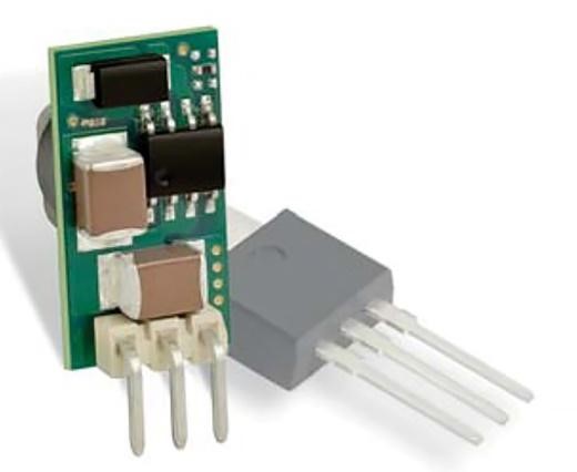
Figure 2: Murata 78SR series buck converter for 0,5A current rating.
While this plug-in device can outperform a linear regulator in terms of efficiency, its performance can be further enhanced by surface-mount DC/DC point-of-load modules supplied in land-grid array (LGA) packages. Murata's MYMGA series, for example [2], reaches an efficiency of 94% for its current with the maximum load of 4A (5V version). The package size is only 9mm x 10,5mm x 5,5mm.
At high power, multiphase buck converters spread the stress of components on switches and duplicated inductors and controlled over two or more phases with common input and output capacitors. To improve their efficiency, these reducers also use synchronous rectification so that the rectifying diode, with its fixed voltage drop, is replaced by a MOSFET whose on-resistance is low.
Isolation is often needed
The simplest buck and boost converters do not provide galvanic isolation, but their input and output grounds are connected. It is often necessary to break this connection to allow the output to "float". This could be because the input takes an unsafe voltage as a reference in order to avoid ground currents or simply so that the output can be configured as a negative voltage by connecting the positive to ground. The isolated topologies equivalent to the buck and the boost are the forward and flyback converters (Figure 3), which can be seen in operation as an inductor serving as a transformer, so an isolated winding can supply the DC output. Observe the adjustment of the phases in the windings of the transformer.

Figure 3: Diagrams of the reverse or flyback (left) and direct or forward (right) converters.
Isolated DC/DC converters are more difficult to fully regulate as the output voltage has to be sensed and an error signal has to pass through the isolation barrier to the primary to control the duty cycle. However, sometimes regulation is not needed; if the input DC is constant, only load variations affect the output, which might only change by a few percent which is usually acceptable. One of the main applications for small isolated DC/DC converters is powering isolated data interfaces where regulation is not required. When the input DC varies, a “semi-regulation” can be used, that is, to detect a primary winding of the transformer as if it were the output. However, to obtain a better accuracy, the output voltage is sensed directly and an error signal is sent to the primary, generally by means of an optocoupler.
When isolation is required for protection reasons, separation and isolation become complicated. The distances in air and creepage lines, as well as the distance from solid insulation, depend on the level of protection required (basic, double or reinforced, for example) and on other parameters such as the degree of environmental contamination, the overvoltage category of the entrance and even the altitude. The application determines the standards applied, for example for patient connection in the medical field, which requires a greater separation distance than the industry. There may be some confusion about the degree of isolation; Devices with an isolation voltage of say 3kVDC are often advertised in production tests, which may seem adequate for isolating 230VAC. However, this is only a test voltage obtained from time to time and does not guarantee that this device will withstand such a high voltage continuously. Users should seek certification from a safety agency that specifies the level tested and what "system voltage" refers to. A DC/DC converter that isolates a circuit that references the 230VAC mains voltage of the connections that a user may touch in a home or office environment, could display “reinforced insulation/ 250VAC at a maximum altitude of 5000m” according to EN 62368-1, the reference standard for safety in Europe.
La Figure 4 is an example from Murata's NXJ series of a buck-derived unregulated DC/DC converter (actually a push-pull) that simply converts 5V to 5V with isolation certified for medical applications. This product applies a novel method that consists of incorporating the transformer core into the layers of the printed circuit board, so that the winding formed by the passage channels and vias of many layers of the board.

Figure 4: Murata's NXJ series consists of surface mount DC/DC converters with certified insulation.
Resonant converters are efficient
The forward converter is available in many versions with different advantages and disadvantages, often determined by the trade-off between efficiency, cost, and application size for a given power and voltage conversion levels. To optimize efficiency, “resonant” converters whose switching is “soft” are often used; that is, they switch while the current or voltage is zero. This eliminates momentary spikes in dissipated power if high voltage and high current coincide. There are many resonant topologies but one currently widely used for low and medium powers is "LLC". This circuit applies pulses to an LC tank, typically just above its resonant frequency, which are then passed as sine waves to a load winding on the secondary inside the tank's inductor by the action of the transformer. Regulation is achieved by varying the frequency of the pulse, which transmits more or less energy through the transformer as a result of increasing the inductive impedance of the LC circuit with a frequency higher than resonance.
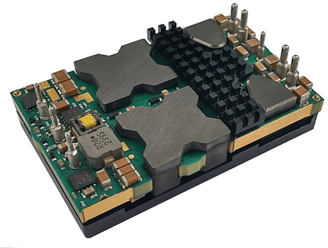
At high power, the stress on the LLC switching transistors becomes unacceptably high, so a “phase-shifted full bridge” topology is often used. This is another resonant circuit in a bridge configuration with four switches but it operates at a fixed frequency and regulation is achieved by varying the relative phase of the control waveforms on each leg of the bridge. This technology is used in Intermediate Bus Converters such as Murata's DRQ series.[5]
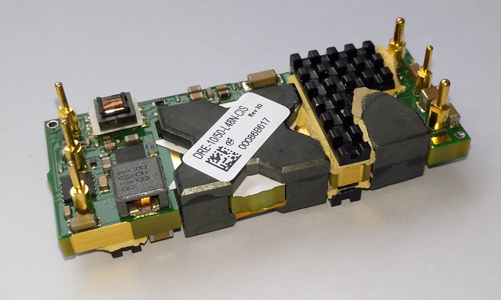
Figure 5: Murata's DRE range.
Switched capacitor DC/DC converters do not require magnetic components
A non-isolated DC/DC converter does not need an inductor or transformer: a switched capacitor topology can be used with load capacitors connected in series or parallel and placed in parallel or series to step down or step up the voltages, respectively, in discrete multiples. Previously voltage drops across switches and diodes have limited efficiency but with modern MOSFETs and synchronous rectification it can exceed 96% at 72W as is the case with Murata's novel Psemi switched capacitor technology (Figure 5) [3]. Usually the regulation is not active and the lowering or raising follows a fixed ratio, 3 or 4 in [3] but the inducerless technique lends itself to modern manufacturing methods and low profile products.
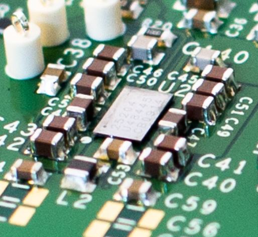
Figure 6: Murata Psemi Switched Capacitor Technology.
Mobile phones demand conversion with maximum efficiency
Lower power non-isolated DC/DC converters are often used in many widely used electronic devices, such as mobile phones, where long battery life is important. This is facilitated by the high efficiency of all stages of the power conversion. Converters that regulate an output when the input is higher or lower than the output voltage are especially valuable as a battery loses charge and its output voltage drops. These converters are often called buck-boost converters, although being strict they provide a negative output that is not always useful. The SEPIC converter mentioned above (Figure 5) is widely used to supply a positive voltage when the input is higher or lower than the output. Q1 in the following schematic works as a synchronous rectifier. L1 and L2 can be separate inductors or wound on the same core.
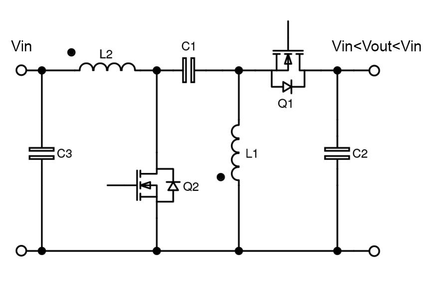
Figure 7: The SEPIC converter works with an input voltage higher or lower than the output.
Inverters with a very wide range of DC input voltage
Having a single DC/DC converter that can work with multiple battery voltages can simplify applications where the equipment manufacturer is unsure which battery the customer will use; For example, in railway applications the battery can be anywhere from 24V to 110V depending on the locomotive manufacturer and geographic region. Murata's IRH250 / IRQ150 converters solve this problem with their 16V – 160V DC input voltage range.
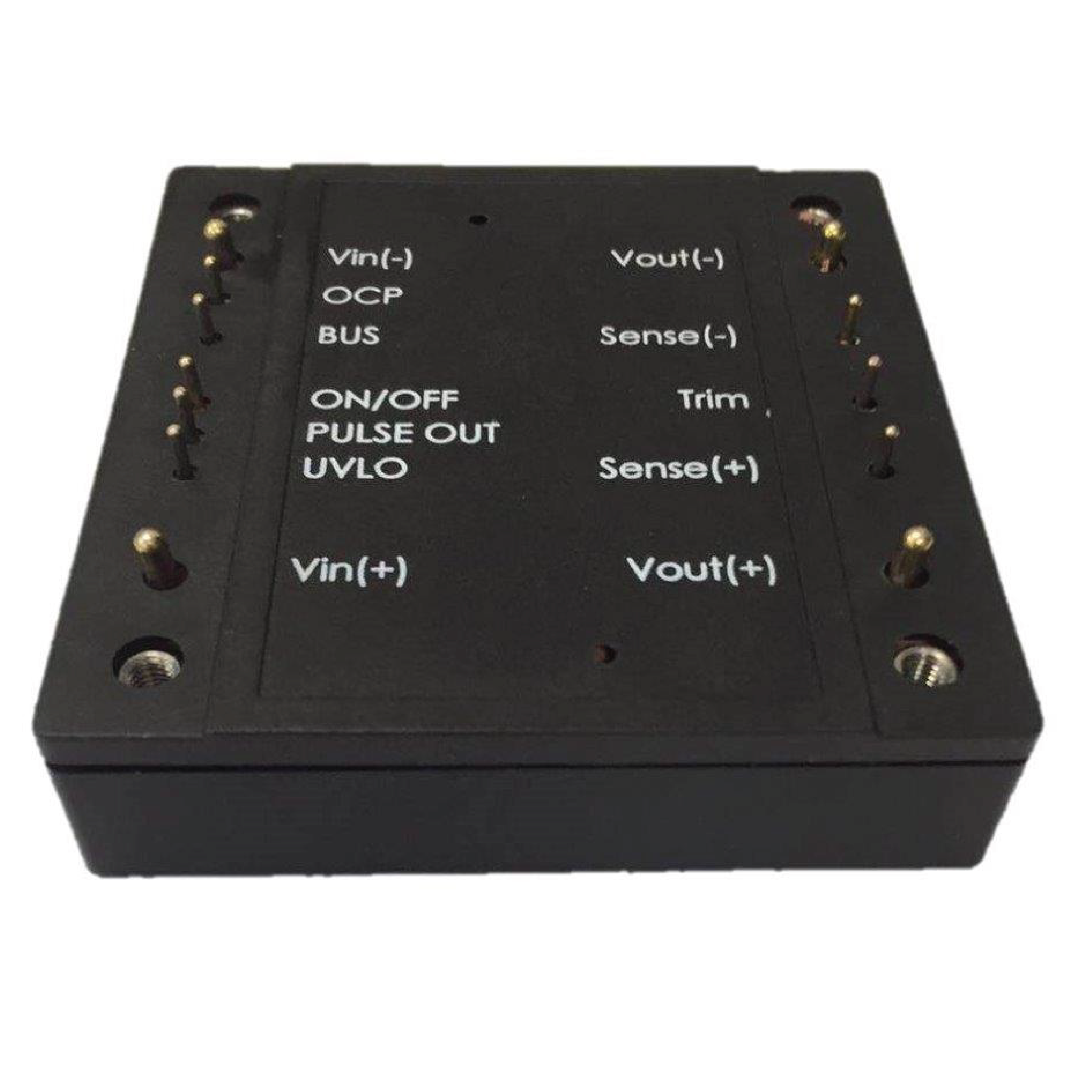
Figure 8: Murata IRH250 drives with a very wide range of DC input voltage.
Automotive requirements are demanding
Small DC/DC converters used in automotive systems can be subjected to harsh environments and heavy electrical demands. Automotive AEC-Q test requirements are not typically applicable to power converters, so they are often classified as “multi-chip modules” for AEC-Q104. The device manufacturer must also be TS 16949 certified for its quality management system, which is much more stringent than the well-known ISO 9001 standard. The Murata NXJ series shown in Figure 4 is an example of an AEC-Q104 certified device. .
This article has briefly reviewed the topic of CC/DC conversion but hopefully shed some light on the types of designs, their features, and their applications.


