Introduction
Thanks to the continued application of Moore's Law and the spread of the affordable microcontroller, we all now have a wide variety of electronic products that incorporate more and more features and functionality. To function, these feature-rich products require better quality DC power than their predecessors. One of the difficulties faced by designers of these products is to provide "clean" sources to the devices and the circuits that compose them.
The study of the efficiency in the delivery of DC power from the output of DC/DC converters to the input of circuit devices is called “power integrity”. Real-time oscilloscopes are commonly used to measure ripple, noise, load response of transient signals, and many other power integrity parameters. This article will demonstrate how analytical data on the possible sources of noise from power supplies can be obtained using the FFT and trigger capabilities of the oscilloscope.
The problem
The importance of a “clean” diet has grown in proportion to the density and speed of successive generations of designed products. Deviations from DC power rails are perhaps the single greatest source of clock and data jitter in digital systems. This process is called power supply induced jitter. A drop in the power supply that powers a digital device can reduce the propagation delay to the device inputs, resulting in reduced sync margin or even bit misses.
As the switching speeds and slew rates of digital devices have increased, so has the likelihood of induced switching noise in the power supply. The resulting noise occurs at the frequency of the switching current, and can easily be higher than 1 GHz.
Improving energy efficiency or reducing energy consumption are other tasks facing designers. To reduce power density and keep power consumption at acceptable levels, designers have lowered the DC operating voltage or tightened the tolerances of the DC sources. For designers, the challenge is to measure ever smaller and faster AC signals passing through their DC sources.
Noise from DC power supplies
Ideally, DC power supplies should not register any noise. And how do you get that?
To begin with, there is Gaussian noise at the source which is a consequence of unavoidable thermal noise, namely electronic noise generated by the thermal agitation of electrons. As a rule, it is not what causes the most noise.
The main sources of noise in DC power supplies are switching noise from the supply itself and noise induced by switching currents from circuit devices, which create transient current demands. The noise created by switching events can appear random in time. However, it is usually consistent with system clocks.
If we think of DC source noise as a combination of “signals” (such as source switching noise and switching current noise) superimposed on the DC source, it becomes easier to measure and analyze.
Given the wide bandwidth of DC power supply noise, people who measure this noise often choose the oscilloscope because of its wide bandwidth, ease of use, and ready availability.
Using the frequency domain for analysis
Using the oscilloscope's FFT capabilities to view signals in the frequency domain can be helpful in identifying contributing sources of noise from a source.
In this example, we have a switching DC/DC converter that converts 5 V to 3,3 V, and this is what we will pay special attention to. The switch operates at 2,8 MHz. Otherwise, the target product incorporates other 5 V-powered circuitry that operates at a 10 MHz clock.
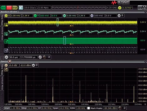
Using the N7020A current rail probe and the Keysight S-Series oscilloscope, we measure the 3,3V source. Simultaneously, we will measure the 10MHz clock (with the standard passive probe). The results of the measurements of the 1 V source and the clock in the time domain are shown in Figure 3,3, together with a frequency domain view of the 3,3 V source obtained using the function of FFT of the oscilloscope. The time domain view of the 3,3 V source allows us to see a signal with a period of about 360 ns that are leftovers from the 2,8 MHz switch. If we compare the time domain view of the 3,3 .10 V with the time domain view of the 3,3 MHz clock, it does not appear that the digital circuitry is contributing to the noise from the XNUMX V source.
Let's look again at Figure 1 and look at the frequency domain. We clearly see spikes that are related to the 2,8 MHz switch (and its harmonics), as well as a spike at 10 MHz that represents clock related noise. Viewing noise in both the frequency domain and the time domain has given us additional insight into the sources of noise.
Using Trigger to View and Measure Signal Components in Source Noise
Using the FFT function of the oscilloscope we have been able to conclude that a part of the noise from the 3,3 V source is related to the 10 MHz clock and the digital circuit of the target product. Knowing this information, the next step a designer can take is to obtain data on how much of that noise is caused by the 10 MHz clock. They can then make an informed decision about the value of a new design to minimize that noise.
Triggering can help to visualize and measure source noise components that are coupled to the source from other system elements with which they are in phase coherence. To demonstrate this, we measure the 3,3 V source and the 10 MHz clock at the same time. Next, we set the oscilloscope to trigger on the rising edge of the 10 MHz clock. Finally, we set the oscilloscope's acquisition mode to analog averaging. By calculating the average of repeated acquisitions, in this case 1024 acquisitions, we will remove all random noise and other components of the signal that are not coherent with the clock. The end result will be the parts of the source noise that are related to the 10 MHz clock. The results of this measurement are shown in Figure 2.
The decision as to whether it is worth doing a new design to minimize or eliminate the noise in our example must be made by the designer, balancing this new noise information with other constraints he or she may have to deal with.
Summary
Identifying possible sources of noise in a DC supply is a critical step for the power integrity engineer or technician. Once the source of the noise is identified, steps can be taken to reduce or eliminate its effect. You can use the FFT function of an oscilloscope to limit and identify potential sources of noise.
The trigger and average can then be used to verify that these possible sources are actually causing the source noise.


