Although digital data transmission protocols have long become standard in process technology, the analog 4-20 mA loop is still current. The millions of times established “rail network” not only serves excellently for the “transport” of analog sensor data, but also for the transmission of digital information. However, it is necessary to supply the electronic system with power on the transmitting side. But what do you do when the meager reserves of loop current aren't enough, and other power sources are out of reach? Now introducing an innovative switching regulator that triples the current performance of 10mA current!
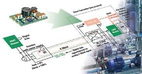
At 70 years old, the analog 4-20 mA loop is past a good retirement age, but it's still very topical. Because it is for process technology exactly what the USB bus is for electronics: A global standard with a relatively simple structure that serves as a guiding basis for everyone! A successor is nowhere in sight and neither is sought. Thanks to “digital upgrades” in the form of signal processors and HART modems, “intelligent” sensors can also be integrated into the system, thus preparing the loop for the future. But let's go back to basics: Whether it's flow, pressure, fill level, humidity, temperature or other physical quantities that need to be monitored. The connection between sensor and receiver is always based on a simple two-wire technique that does not transmit the signals as voltage, but as applied current. By definition, 4 mA corresponds to the value of 0% and 20 mA to the value of 100% (Fig. 2). This scheme implies a number of advantages. The length of the cables can be chosen freely, as long as the loop voltage is large enough to carry at least 20 mA of current through the line. The current impulses are resistant to all types of interference sources in an industrial environment, so the requirements for the cabling are relatively uncritical. Therefore, the signal lines must not be separated from the electrical cables. This greatly simplifies wiring in large installations, such as in the petrochemical industry, where sensors can be hundreds of meters apart, while reducing costs. Since a current always flows in the system as a “sign of life”, fault monitoring is automatically included. If no current flows, the measured value is not "0 %", because the connection is interrupted or the sensor is faulty! However, there are critical shortcomings. What is very disturbing is that each sensor needs its own cable. This is where digital technology steps in and provides a key “upgrade”. In a modern version of the 4-20 mA loop, data from multiple sensors is processed by the DSP and sent in parallel as a frequency-modulated pulse packet over the analog line. This requires HART (Highway Addressable Remote Transducer) modems that add the digital signals on the transmitter side to the analog signal and then decouple them again on the receiver side (Fig. 3). In this way, both are available separately in the control center. This is important when you need to respond to changes via a decoder in real time, without any delay. HART technology is by far the most widely implemented data protocol in the process industry today and has been instrumental in making the 4-20 mA loop future-proof.
Smart Power for Smart Transmitters
While the supply of a 4-20 mA loop is carried out on the receiving side and is not problematic, because voltages between 12 and 36 V from any power supply are sufficient, the current resources are subject to restrictions on the transmitter side. This did not produce any problem in “analog times”, since the sensor had practically no electrical demand. But times have changed. Although it is true that the <4mA available capacity of the loop is usually enough to compensate for the jumpers or to supply the op-amp. But when it comes to digital components like DSPs, modems, and displays, the allowable limit of 4 mA is quickly exceeded (Fig. 4). If a corresponding power supply is nearby, this does not cause a conflict. But if the transmitter is "remote" somewhere in a boiler, the expense is correspondingly large. It is more sophisticated in this case when the electronics can be supplied with power from a loop. One solution offers the use of switching regulators that are known for their high efficiency. Because as real "power converters" they are capable of converting a higher voltage at the input to a higher current at the output. And that's what's required when you want to “pick up” more current from a 4-20mA loop than the <4mA systemic limit offers. However, switching regulators have to date been designed exclusively for significantly higher currents. In known topologies, the self-consumption in no-load conditions is already significantly above the permissible limit of <4 mA. But even if it were still below that, another technical hurdle would need to be faced. Because switching regulators transport power from the input to the output in pulses. Since the peak values must remain below the 4 mA limit, only part of the potentially available power can be used. It is necessary to break completely new ground in order to be able to implement switching regulator technology sensibly in “low power” applications despite high hurdles.
New technology reduces no-load current to 100 μA
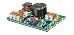
A new topology of switching regulators for “low power” applications has been developed in the main RECOM laboratory in Gmunden. The new product is presented under the name R420-1.8/PL on the market and will soon be available as a design pattern (Fig. 5). The quiescent current dropped to around 100 uA and is no longer important in practice. At the output there is a current of 10 mA. This is three times what has been achieved with linear regulators. Another advantage: The new technology allows the output voltage to be programmed via an external resistor in the range between 1,8 V and 5 V. Users can therefore solve different tasks with the same components. By means of a limited switching frequency to just under 50 kHz and correspondingly careful filtering, residual ripple and noise could be limited to very good values per d
below 30 mVpp. In addition, the developers have succeeded in designing the input circuit in such a way that current pulses are largely offset. Thus the 3,6 mA loop current can be used effectively without affecting the <4 mA threshold. The 10 mA available at the output is generally enough to supply electronic components, such as DSPs, HART modems, or displays, with sufficient power from the loop. Conclusion The fact that the R420-1.8/PL with identical power consumption at the output makes 3 times more power available than the previously available linear regulator opens up a wide range of additional applications in loop “digitization”. 4-20mA. This makes the sensors even more intelligent and ensures the continuity of this extremely popular interface for decades to come. The use of this interesting module, however, is not limited to process technology only. Also in other areas, such as IoT (Internet of Things), there are applications where only low power is required for the supply of electronic components. This is where RECOM's new “low power” R420-1.8/PL switching regulators can be valuable.


