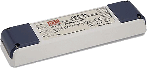
In November 2014, the second edition of the DALI standard, also called DALI-2, was published. One of the main objectives of this version was to eliminate several existing ambiguities in the standard available up to now (Edition 1) and ensure better interoperability between devices from different manufacturers. While Edition 1 mainly established the general bases of DALI communication (part 101) and defined the requirements for control gear (part 102) such as drivers and electronic ballasts, Edition 2 adds a new specification for control devices. (part 103) in addition to a deep revision of the parts that Edition 1 already contained.
Control devices are basically devices designed to communicate with control gear such as sensors, pushbuttons, switches... The original DALI standard specified the commands and configuration options of the control gear, however the communication between them and the control devices as well as between various control devices was not yet defined. Through Edition 2 of the DALI standard, the particularities and communication of these control devices are clearly specified.
Two categories can be distinguished within the control devices: “Application Controllers” and “Input devices”. “Application Controllers” are those devices that can send control commands to the control gear, for example a sensor that sends a dimming command to the luminaires connected to the DALI bus. Configurable control devices such as DALI masters, gateways or push button modules usually also have an "Application Controller" implemented, since they are capable of sending lighting control commands by themselves. Within the “Application Controllers” we can also distinguish between “Single Master Application Controller (SMAC)” and “Multi Master Application Controller (MMAC)”. When we use a SMAC, the DALI bus is controlled only by this device, since this type of "Application Controllers" cannot recognize if other control devices are sending a command over the DALI bus, so if they are combined with other control devices in the same bus would produce a collision of the commands (figure 1) making said communication unreadable for the system. Therefore, it is not possible to add any control device to a system that already has a “Single Master Application Controller (SMAC)” installed.

On the contrary, as shown in figure 2, when we use a MMAC we can add other control devices to the same DALI bus so that they all control the lighting simultaneously. This is because this type of device includes message collision detection and is capable of monitoring the DALI bus to send its commands only when it is free and there is no communication.

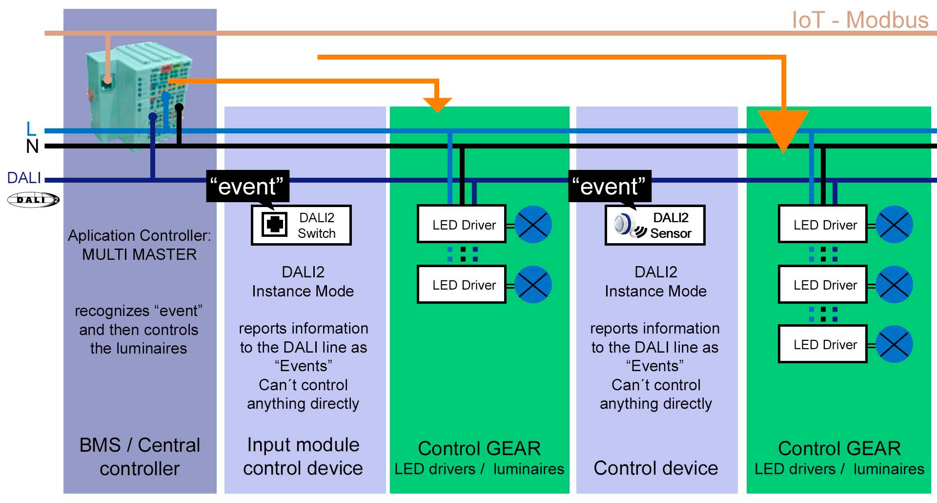
On the other hand, the control devices categorized as "Input devices" are those devices that only send information to the DALI bus in the form of events in such a way that an "Application Controller" can receive these messages, interpret them and control the lighting based on they. These types of devices cannot control lighting directly as they are not capable of sending control commands by themselves. The configuration mode of the "Input devices" to carry out this sending of information to the DALI bus in the form of events is called "Instance mode".
As can be seen in figure 3, a presence sensor configured in "Instance mode" sends an event when it detects presence so that a DALI master type central control unit can interpret said message and send the appropriate regulation commands to the luminaires.
The events mentioned above are fully defined in the DALI-2 specifications (parts 301-302-303-304) for devices such as pushbuttons, presence sensors, light sensors...
There are control devices on the market that combine both control categories, that is, they are considered as "Application Controllers" and "Input devices" at the same time. This implies that this type of device can directly send control commands as well as information in the form of events to the DALI bus to be interpreted by other "Application Controllers".
Within the term "Instance mode" it is important to highlight what the DALI standard defines as "Instances" or instances. Each "Instance" refers to a functionality of an "Input device". For example, a presence and luminosity sensor would have 2 different "Instances" (one for the presence functionality and another for the luminosity functionality). Another example would be a module with 4 buttons, which would have 4 “Instances” in total (one for each button).
The “Instances” are generally used to integrate the “Input devices” in a system with a DALI-2 central control unit. The value/status of the "Instances" can be requested by said central control unit or they can be configured to send their value periodically. The “Instances” can also be activated/deactivated, filtered, grouped and prioritized based on the particular requirements of each system.
Currently, the DALI-2 standard defines four types of "Instances":
- Instance Type 1 (IT1):Pushbutton.
- Instance Type 2 (IT2): Analog input.
- Instance Type 3 (IT3): Motion detection.
- Instance Type 4 (IT4): Light intensity measurement.
Before delving into the particularities of each type, we must define some key configuration parameters that are common to most of them:
- EventFilter: Selection of events available for each type of "Instance". When the value of the activated events changes, said information will be sent to the DALI bus.
- dead time: Determines the “dead” time that must elapse until an event can be sent again. This parameter is also effective even if the value of the events changes.
- Report Time: Configures the time for sending events periodically regardless of whether or not there is a change in their status.
INSTANCE TYPE 1 – PUSHBUTTON

The devices that make up the IT1 are mainly pushbuttons and pushbutton modules.
The events/states available (Event Filter) for IT1 are the following:
- Button pressed: When the button is pressed.
- Button released: When the button is released.
- short press: When the button is pressed and released quickly (short press).
- double press: When the button is pressed, release and press again quickly (double press).
- Long press start: When the button is pressed and held down (long press start).
- long press repeat: After the previous event, it is sent periodically for the duration of the long press and until the next event occurs.
- long press stop: When, after the long press start event occurs, the button is released (long press end).
- Button stuck/free press: When the button has been pressed for a long time and it is assumed that it is stuck.
The following table (figure 4) shows, in addition to its description, the number corresponding to each event in the "Event Information" column:

As can be seen in figure 5, the number associated with each event can be very useful when monitoring the DALI bus traffic in an installation since, depending on the software used, sometimes the complete name of the event is not represented in the interface:

On the other hand, for IT1 there are a series of configuration times (Event Timer) for the events described above:
- short press timer: Maximum duration of the press to be considered as a short press.
- double press timer: Maximum time between two clicks for it to be considered as a double click.
- repeat timer: Time between sending “Long press repeat” events during a long press.
- Stuck timer: Time that the button has to remain pressed for it to be considered stuck.
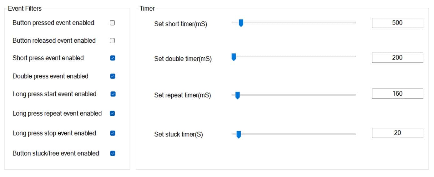
Figure 6 shows the configuration options "Event Timer" and "Event Filter" for an IT1 in the Meanwell DALI configuration software DLC-02:
INSTANCE TYPE 2 – ANALOG INPUT

The devices that make up the IT2 are mainly panels with sliders, rotary regulators and different types of sensors. The status of these "Instances" correspond to the position or value delivered by the aforementioned devices. For example, if the position of the wheel of a rotary regulator or the measurement delivered by a temperature sensor changes, the associated "Instance" will generate an event on the DALI bus.
The events/states available (Event Filter) for the IT2 depend on the type of associated device, although they always refer to its position or measurement value. Here we will mention some examples:
- touch panel slider: Position of the slider when clicking on it.
- Rotary Button: Position and movement of the regulator rotary knob.
- Temperature sensor: Measured temperature value.
- Humidity sensor: Measured humidity value.
- air pressure sensor: Measured air pressure value.
- air quality sensor: Measured air quality value.
For IT2 we can also configure the “Report Time” and “Dead Time” parameters described above at a general level.
Figure 7 shows the configuration options "Event Timer" and "Event Filter" for an IT2 of a Touchpanel Slider in the DALI configuration software DLC-02 from Meanwell:

INSTANCE TYPE 3 – MOTION SENSOR

The devices that make up the IT3 are mainly presence sensors.
The events/states available (Event Filter) for IT3 are the following:
- occupied: When it is determined that the room is occupied.
- Vacant: When it is determined that the room is empty.
- Still vacant/Still occupied: When it is determined that the room is still empty/occupied.
- Movement: When motion is detected.
- No movement: When no motion is detected.
For IT3 we can also configure the "Report Time" and "Dead Time" parameters described above at a general level. There is also a specific parameter for IT3 called “Hold Time” which refers to the time that must elapse from when movement is no longer detected (“No movement” event) until it is determined that the room is empty (“Vacant” event) , this term could be compared to the persistence time/linger time of a lighting state triggered by the action of a presence detector.
To represent these concepts in a more intuitive way, figure 8 shows all the events and parameters described during the actuation of a DALI-2 presence sensor configured in "Instance mode":

Figure 9 shows the configuration options "Event Timer" and "Event Filter" for an IT3 in the DALI configuration software DLC-02 from Meanwell:

As in the previous example, it is quite common that only the “Occupied” and “Vacant” events are enabled during IT3 integration to simplify control and limit traffic on the DALI bus.
INSTANCE TYPE 4 – LIGHT SENSOR
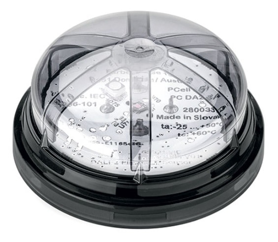
The devices that make up the IT4 are mainly light sensors.
The only event/status available (Event Filter) for IT4 is the following:
- light value measurement: Measured lighting value (lux).
For IT4 we can also configure the parameters "Report Time" and "Dead Time" described above at a general level. There are also two specific parameters for IT4 called "Hysteresis (%)" and "Hysteresis min (lux)" which are related to the percentage (%) and minimum value (lux) of hysteresis necessary for an event to be resent when it varies the measured light level.
Figure 10 shows the configuration options "Event Timer" and "Event Filter" for an IT4 in the DALI configuration software DLC-02 from Meanwell:

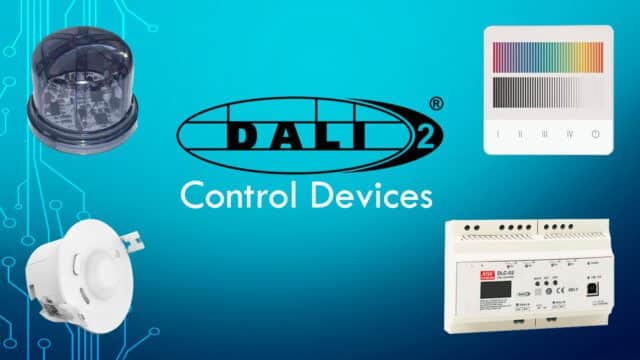
At Olfer Electronics we have a wide variety of DALI-2 control devices, both “Application Controllers” and “Input Devices”. Many of them can be integrated with Meanwell's new DALI-2 central control unit called DLC-02 and compatible with all instance types and configurations mentioned in this article to provide maximum flexibility when adapting the control of lighting in a DALI-2 system to the needs of any installation.


