In the electronics industry, reduced power consumption and increased data rates continue to force lower power rail voltages. In line with these lower amplitudes, more stringent specifications for power supplies and supplied power are being applied. Oscilloscopes remain a valuable tool for measuring power rail characteristics such as transient response and drift, both periodic and sporadic. Various probe options are available to make these measurements, from blocking capacitors to active probes, each with advantages and disadvantages. Also, the physical connection of the probe can affect the quality of the measurement. Input load, noise, and offset are important issues when probing DC power supplies. Understanding and evaluating these probing factors is crucial to obtaining the best signal integrity (SI).
At first glance, DC power supplies seem like simple components within the ever-increasing complexity of today's world of electronics. However, as microprocessors and RF chips continue to reduce their power consumption and increase their data rates, the demand for circuitry to power them increases. A source must offer stable and accurate voltage and current, regardless of its variable load. Voltage rail designers are under pressure to tighten voltage tolerances and remove unwanted signals from their sources. Accurately measuring characteristics such as PARD, noise, and dynamic response is critical in today's power supply designs. Power supply designers in nearly every industry in electronics use oscilloscopes to view variations in power rails over time. Because these variations are often small in amplitude, down to tens of millivolts, measuring a power rail with an oscilloscope probe can be difficult. Scope and probe noise can mask the signal, and an insufficient physical connection can degrade the entire measurement.
The requirements for probing a power rail are much the same as for any other signal, although with a few key differences. Noise, load and offset are the main issues. As with most probes, as little loading on the probe as possible will be desirable, although loading at low frequencies is important when measuring sources. Power rails are less sensitive to probe loading, as they tend to have low source impedance. However, as with other signals, minimal probe loading is desirable at low frequencies, especially DC, so that the probe does not draw appreciable current from the source.
In order to accurately measure small voltages, noise is probably the biggest problem with power rail probing. Although the DC voltage of a source can be a fundamental measurement, the output of the source is not perfect DC. AC noise and transient responses to variable loads are the main concerns when analyzing power rails. Specifications such as PARD must be measured in real time, so their averaging is not practical. In order to accurately quantify the ripple and noise characteristics of the source, the noise generated by the oscilloscope measurement must be minimized. Understanding what noise the measurement itself adds, such as scope noise or probe attenuation, is critical to obtaining optimal measurements.
Finally, the probe offset range can play a key role in minimizing noise. In order to measure the source at the lowest noise settings of an oscilloscope, the probe needs a suitable offset range. By adapting the probe offset to the DC voltage of the source, it is possible to center the signal on the oscilloscope screen with maximum zoom; thus, the oscilloscope will normally have no attenuation and therefore offer as little noise as possible. A wide range of offset will allow thorough inspection of different sources, regardless of DC voltage.
There are several probing options for measuring power supply rails on an oscilloscope. No method is perfect and all have advantages and disadvantages. Perhaps the most common technique is to use a blocking capacitor or AC coupling mode on the oscilloscope. In this way, the rail can be directly probed with a lead into a 50 Ω input. The main advantage of this method is that the oscilloscope can measure almost any DC voltage with high sensitivity. The biggest drawback is that the low frequency content is not observable. Power supply designers often need to analyze slow variations in long transients. If the frequency of the variation is below the cutoff point of the filter, a blocking capacitor will not allow these behaviors to be observed.
Another common technique is to probe the source with a 50 Ω cable directly into the 50 Ω channel of the oscilloscope. By adapting the oscilloscope channel offset to the DC voltage, the signal can be viewed using the minimum attenuation, minimizing the noise contributed by the oscilloscope. This method also allows observing DC content and frequencies up to the bandwidth of the oscilloscope. If the oscilloscope bandwidth is much larger than the frequencies of interest, the channel bandwidth should be reduced to minimize the noise contributed by the oscilloscope.
However, using a 50 Ω cable directly into the channel of an oscilloscope has certain drawbacks. Perhaps the biggest is the limited offset range that the oscilloscope exhibits at high sensitivities. As the volts per division setting on the oscilloscope channel is minimized, the offset range is also reduced. If the oscilloscope does not have a sufficient offset range to accommodate the DC voltage of interest, the only option is to increase the volts/division ratio, thus increasing measurement noise. Another major drawback of this method has to do with charging. The source must supply current for an additional load of 50 Ω in DC. Depending on the design, this additional load could cause the source to behave differently than it would without the 50 Ω DC load. In this example, the 50 Ω load may cause a lower output voltage from a linear regulator. In contrast, in designs with a smaller margin or greater complexity, this behavior can be more unpredictable.
Another option available for probing power supply rails are active probes. Both unipolar and differential active probes can be used for this measurement. By adapting the probe offset to the rail DC voltage, the signal can be viewed with high sensitivity.
When using an active probe to measure a power rail, we must take several factors into account. Active probes offer different offset ranges, so it is important to use a probe with enough offset to cover the power rail voltage range. Another problem with using an active sonar is input noise. Most active probes feature attenuation to maintain viable input ranges. The probe attenuation increases the noise referred to the input, since it multiplies the noise of the oscilloscope by its attenuation factor and this is added to the noise contributed by the probe. Typically, active probes with attenuation will have much higher input-referred noise than a blocking capacitor or direct 50 Ω channel. Since the attenuation of a probe often contributes noise referred to the input, a probe with a 1:1 attenuation is usually preferable when probing power supplies. Although active probes offer several key advantages, such as minimal head and long input range, they are often undesirable for probing power rails due to their higher noise.
Demand is beginning to exist for probes specifically designed to measure power supplies, which sacrifice some of the general-purpose capabilities found in traditional active probes in favor of features that make them ideal for power supply measurement. They offer very low noise, minimal DC load, large offset, and a wide input range. An example of these probes is the N7020A from Keysight Technologies. With 1:1 attenuation and a 50 kΩ DC resistor, it can measure broadband content, including DC up to ±24 V, with minimal noise and load. For power rails, this probe offers many of the advantages of the probing techniques described above and almost no drawbacks.
As we have already mentioned, charging is a problem for power rail measurements, especially at low frequency. Figure 1 graphically shows the probe load according to the different options that we have tried. Since most power supplies have a low input impedance, they will be hardly affected by the probe load at high frequencies. The 50 Ω cable will draw substantial current at DC, unlike the other probes. The active probe is the only option shown in Figure 1 that maintains a low load even at high frequencies. While this is important in other general polling applications where the input impedance may be higher, it is usually of no advantage for power rail applications as the source impedance is low.
All of the probing options described above have one thing in common that can have a major impact on signal integrity: the first half centimeter of the probe. As long as the amplitude of the signals of interest is low, the quality of the physical connection of the probe can have a strong impact on the integrity of the measurement.
Noise in the measurement can be caused by the oscilloscope and the probe, it can be part of the signal at the probe tip, or it can be the result of an external influence due to a lower connection. There are two main sources of noise caused by incorrect grounding. One is ground loop injection and the other is electromagnetic pickup. Excessive length of the probe signal or ground connection will make both cases worse.
Ground loops are often a problem with single pole probes. These are formed when one or more ground paths join at two or more points. They cause measurement problems when the ground potential of the device under test is different from the ground potential of the oscilloscope chassis. In such a case, the current drops through the ground shield of the probe, causing a signal to appear on the screen. To determine if a ground loop should be a concern, the ground connection of the probe and input must be connected to the ground of the device under test. If a signal appears on the oscilloscope, the ground loop must be removed. This can be done by improving the ground connections of the device under test and the oscilloscope on the bench or by connecting the oscilloscope ground to the device ground with a low impedance path.
Noise can also be due to electromagnetic interference. In this case, the ground wire works like a single turn loop antenna. Any nearby circuits that emit electromagnetic energy could be picked up by the probe and appear on the measurement. If moving the ground lead changes the nature of the noise, the problem is likely one of noise pickup. Another method of determining the source of the noise is to disconnect the probe from the DUT and connect the input to the work lead. Functioning like an antenna, the probe tip can be moved around various potential sources to identify those radiating energy.
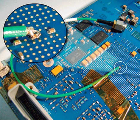
For single pole measurements, a prepared coaxial transmission line, also called a pigtail, often provides the best physical connection for measuring power rails. As seen in Figure 2, the pigtail probe has a protruding center conductor and an exposed tinplate outer shield, which facilitates soldering between the voltage rail and ground. With hardly any excess ground length, ground inductance is minimized.
In addition, the loop area between the center conductor and ground is reduced, making the connection less likely to be subject to external influences. Often a bypass capacitor is suitable for probing a rail with a pigtail probe. The center conductor can be soldered to the supply side of the bypass and the shield can be soldered to the ground side, as shown in Figure 2.
The oscilloscope is a valuable tool when analyzing power supply designs. As the requirements placed on the specifications of the sources increase and the voltages of interest are reduced, the integrity of the signals becomes of fundamental importance. Different probing methods, from blocking capacitors to active probes, offer advantages and disadvantages. Factors such as input load, noise and offset must be taken into account when choosing a probe. In addition, the physical connection directly affects the quality of the measurement.
Minimizing the length of the ground connection is essential to maintain the best noise level. When measuring power rails, it is important to understand the trade-offs that various probing techniques and their connections represent.


