A common electromagnetic compatibility (EMC) problem is having excessive common mode currents in conductors. These problems can arise at the PCB level, at the level of the internal and external wiring of the equipment, or at the level of the installation of a system in general. Electromagnetic interference (EMI) in common mode is often due to reasons that are not very obvious, such as the noisy ground of the circuit, the couplings due to parasitic capacitances, the lack of sufficient decoupling in the power supply, or unbalances in the paths of the differential signals in the switching power supplies, etc. It is therefore parasitic circuits that are not evident, as they are not reflected in the schematics. But we must bear in mind that they always exist to a greater or lesser extent.
One of the most effective techniques to control common mode currents is the use of common mode chokes (CMC). In the radio world, this component is also called a BALUN (“BALanced-UNbalanced transformer”).
An advantage of CMCs is that they present a high series impedance to common mode interference currents in the circuit and this impedance does not affect the differential functional signal. Figure 1 shows the direction of currents in differential mode (MD) and in common mode (MC) in a CMC. In a CMC, the desired signals in MD pass without being attenuated as they have hardly any impedance in MD, while the EMI in MC remain attenuated as they present a high impedance in MC.
To obtain a high effectiveness of the CMC it is necessary to have high permeability in a core. Typical core relative permeability values are on the order of 2000 for low frequency applications and 100 to 200 for high frequency applications. This high permeability results in a high inductance. It is possible to obtain attenuation values of 80 to 100 dB beyond the cutoff frequency of the shock.
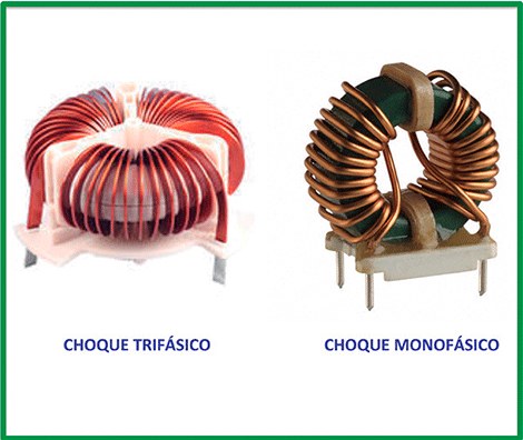
The main advantage of the CMC is its ability to attenuate high frequencies, with virtually no effect on differential mode signals. In addition to their use in single-phase filters, they can also be used in three-phase filters with three windings on the same core (figure 2). These two chokes have separate windings. Another advantage of the CMC is its ability to pass direct current without the risk of saturation, thanks to the cancellation of the induced current flow in differential mode.
This does not happen in isolation transformers. In CMCs, the differential mode is also important due to imperfections in the symmetry of the windings.
Usually, the types of core most used in the realization of CMC are toroidal cores, “E” type cores and “pot core” type cores. Figure 3 shows these cores and their assembly.
Figure 4 shows a comparative table of the main characteristics of these three most used types of core. Ferrites provide high permeability up to a cut-off frequency in the range of kHz to MHz. Above the cut-off frequency the attenuation effect is strongly reinforced by magnetic loss. The filter designer has to deal with large material tolerances of up to 25%.
As in isolation transformers, parasitic capacitance limits high frequency performance. CMCs can also be susceptible to interference due to external magnetic fields, although to a lesser extent compared to an isolation transformer.
parasitic capacity
Every CMC has some parasitic elements whose equivalent circuit is presented in figure 5. In series with each coil we have a parasitic series resistance that is very low (R1 = R2 = R) and between the input and the output of the CMC there is a capacitance parasitic C. The load impedance ZMC is the MC impedance of the cable and the VMC voltage is the EMI voltage on the cable. In this equivalent circuit, ZMC is not the impedance at MD. This is the impedance of the cable acting as an antenna and can vary between 35 and 350 Ω. The parasitic capacitance C is the sum of the parasitic capacitances between turns in the coils and between the input and output terminals of the CMC. This parasitic ability is inherent in its construction.
In order not to increase its value, it is not convenient to “closer” the connection islands of the input and output. To do this, it is not convenient to draw these islands that are too large, to keep their distance between the entrance and the exit of the CMC as large as possible. The value of this parasitic capacitance should be considered when the choke is used at high frequencies (> 10 MHz).
The choke insertion loss is defined as the ratio of the MC current without the choke to the MC current with the choke. In the same figure 5 the equation of their insertion losses is presented.
Insertion losses above 70 MHz do not vary much with the value of choke inductance. However, they vary considerably depending on the parasitic capacitance value. It is difficult to obtain insertion losses of more than 12 dB at frequencies above 30 MHz.
MC clashes in network filters
An important aspect in the design of filters for EMI reduction is the determination of the necessary insertion losses in the frequency range below the EMI frequencies. To determine the nominal inductance of a CMC, the desired operating temperature and its influence on the initial relative permeability must be taken into account.
Leakage inductance must also be taken into account in order to avoid saturation and for differential mode interference attenuation.
The design of a network filter is always carried out in sections in common mode (MC) and sections in differential mode (MD). A vital part of the common mode filter is the CMC (Y-capacitors must be added to ground).
Its great advantage, compared to MD inductances, is that very high inductance values can be achieved in a small magnetic core.
One of the main design considerations in a CMC is its leakage inductance, that is, its inductance at MD. The practical method of calculating the leakage inductance is to assume that it is 2% of the inductance in MC. Actual measurements show that the leakage inductance can vary between 0,5% and 4% of the inductance in MC. This considerable margin of error can be significant when it is desired to perform an optimal design of a common mode choke.
The filters are designed with preferably independent MC and MD sections. However, the sections are not truly independent since the CMC can have significant MD inductance. This MD inductance can be modeled as a discrete MD inductance.
To take advantage of the MD inductance in the filter design, the two sections should not be designed simultaneously. It is better to design them sequentially.
First of all it is convenient to design the filter in MC and then it must be measured by using a differential mode and common mode separating network (DMRN). With it, noise can be measured separately in MC and in MD.
When an MC filter is designed to limit MD noise, the summed MC and MD noise must be measured equally. Since the MC EMI component must be below the limits, the emissions that are above the limits are MD, attenuated by the MD leakage inductance of the MC filter. In low power power supplies, the MD inductance in the CMC can be enough to solve the problems of MD emissions, because these have a low impedance in their generator, so even small amounts of inductance are efficient enough. . Having just a little inductance in MD can be very useful, but having too much inductance in MD can lead to core saturation.
Importance of leakage inductance
What causes leakage inductance in a CMC? A toroidal core with a winding tightly wound around its circumference contains all of the magnetic flux within the "core" of its structure, even if the core were air.
If, on the other hand, the coil is not wound around its entire circumference or if it is not wound close to the core, then magnetic flux can leave the core.
This effect is proportional to the relative size of the open gap left in the winding and to the magnetic permeability of the core material.
A CMC has the two windings arranged so that currents flowing through the core in opposite directions cause a net magnetic field H equal to zero.
In mains filters, for safety reasons (insulation), the cores are not wound in a bifilar fashion, and there are not two too large separations in the winding. This physical arrangement automatically gives rise to a stray magnetic flux indicating that the H-field is actually not zero at all points, as expected.
The leakage inductance of a CMC is equivalent to an MD inductance. In fact, the magnetic flux associated with the MD inductance must leave the core at some point. In other words, the magnetic flux lines close off the core, instead of closing on the toroid.
If the core has a certain MD inductance, the MD current causes a flux variation in the core.
If this flux variation is too high, the core becomes saturated. This saturation leaves the inductance at MC essentially equivalent to the inductance of an air-core coil.
The emissions in MC will therefore be at a level as high as if the CMC were not in the circuit. The flux variation in the MC core caused by the currents in MD is:
where:
• dq / dt is the flux variation in the core
• LMD is the inductance measured in MD
• dIMD / dt is the current peak in MD
• n is the number of turns or spirals in the collision in MC
Since it is desirable to avoid core saturation by keeping Btotal less than Bsat, the criterion is:
Where,
• IMD is the peak current in MD
• A is the sectional area of the core
• n is the number of turns or spirals in the collision in MC
• Bmax is the maximum flow change
• LMD is the inductance in MD of the core
The MD inductance of the core can be measured by shorting the ends of one side together and then measuring the inductance of the other two ends.
MC shocks work well because the MC permeability, µMC is several orders of magnitude greater than the MD permeability, µMD and because the MC currents are typically small. In order to increase the inductance in MC while minimizing the inductance in MD, it is preferable to use cores with a larger cross section instead of using more turns. By using a larger core than necessary, a significant MD inductance is added to the MC choke.
Since the flux in MD (scattered flux) exits the core, significant radiated emission can occur. Especially in the case of filters inside the equipment, this radiation can be coupled internally, causing an increase in conducted emissions.
Saturation detection with a LISN
Detection of core saturation in a CMC (full or partial) is sometimes difficult. A simple test can show the level of filter attenuation in MC. The attenuation is affected by a decrease in inductance caused by the 50 Hz current. The test requires an oscilloscope and a Differential Mode Rejection Network (DMRN). First, the mains voltage is monitored by channel A of the oscilloscope. During the peak current of the network, a decrease in the efficiency of the filter is expected. The DMRN inputs are connected to the two outputs (L1 and L2) of the Line Impedance Stabilization Network (LISN). The MC output of the DMRN should be terminated with a 50 ohm resistor and connected to channel B of the oscilloscope. When the CMC is operating in its linear region, the measured emissions on channel B should not increase by more than 6 to 10 dB during the current increase. Figure 6 shows the oscilloscope screen of this test setup.
The lower trace is the emissions in MC; the upper trace is the 50 Hz mains line voltage. During periods of peak line voltage, the bridge rectifier is forward biased and carries the charging current of the large input capacitor (C) of the power supply. feeding in MC (figure 7(a)).
If the CMC reaches saturation, the emissions during the input peak will increase. If the CMC reaches high saturation, the emissions will be almost at the same level as without a filter, that is, easily 40 dB or 60 dB higher. Therefore, saturation should be avoided.
This can be interpreted in another way. The minimum value of emissions (during periods of zero line current) is equivalent to the filter efficiency with zero bias current. The ratio between the maximum emission peak and the minimum emission peak (the degradation factor), is a measure of the effect of the line current on the efficiency of the filter. A high degradation factor suggests lower kernel usage relative to initial usage. If a "natural degradation factor" of the order of 2 to 4 is observed, it is a good filter. Two phenomena contribute to this degradation factor. First, there is a decrease in inductance caused by load currents at 50 Hz. Second, the bridge rectifier (figure 7(a)) is biased by the forward and reverse currents of the 50 Hz sinusoid.
The equivalent scheme for MC emissions (figure 7(b)) consists of a voltage source with an impedance of the order of 200 pF, equivalent to the impedance of the rectifying diode and the common mode impedance of the LlSN. While the bridge is biased, there is a voltage divider between the generator impedance and the 25 ohm LISN MC impedance.
When the bridge is reverse biased, the voltage divider occurs between the impedance of the generator, the capacity of the bridge rectifier and the LISN. When the capacitance of the bridge reverse diode is low, it contributes to the filtering of MC emissions. When the bridge rectifier is forward biased, the bridge has no influence on the filtering of MC emissions. Due to this voltage division, a natural degradation factor of the order of 2 is expected to be obtained. The actual values can vary considerably depending on the actual values of the generator impedance and the capacitance of the reverse diode.
Saturation detection with current probes
Another similar technique can be used to detect saturation of a CMC. The technique is employed as follows. Two current probes are used. With a low-frequency current probe, the input current of the 50 Hz line is controlled and with another high-frequency probe, only the MC emission current is measured.
A potential problem with the use of current probes is that the MD current rejection is highly dependent on the symmetry of the winding in the core. With careful wire placement, approximately 30 dB MD current rejection can be obtained. Even with this rejection, the MD current level can still exceed the MC current level.
A technique can be used to overcome this problem, using a high pass filter with a cutoff frequency of 6 kHz in series with the oscilloscope. This should be terminated with 50 ohms. To measure MC emissions, the current probe is clamped around these cables, which carry very small line currents.
The magnetic flux in CMC and in MD
An easy way to understand the operation of a CMC can be explained as follows: the fields on both sides of the core cancel and there is no magnetic flux to saturate the core. But it's not physically quite accurate. The following argument based on Maxwell's equations should be considered:
- Since a current density produces a magnetic field H, it must be concluded that another nearby current cannot cancel or prevent the presence of a H field.
- Another nearby current can cause a disturbance in the magnetic field lines.
- In the specific case of a toroidal CMC, the MD current density found on each side is assumed to be equal and opposite. Therefore, the resulting field H must sum to zero around the circumference of the nucleus, but not outside the nucleus.
The core acts as if it has been snapped in half between the two coils. Each coil generates its magnetic field in each half of the toroid (dH/dt = 0). It implies that the fields must close in on themselves through the surrounding air. Figure 8 is a drawing of the flow lines of the MD currents in a CMC.
The structure of the nucleus type "pot-core"
To implement an effective MC shock design, the problem of radiation caused by stray flux from the core must be solved. Methods to overcome this radiation problem include containing the MD flux (scattered flux) within the core's magnetic structure (pot-core: Figure 9) or providing a high permeability path for the MD flux. (type “E” core: figure 10).
When using a pot-core to build an MC choke, two coils are used. Figure 9 shows the flow lines in MC. It also shows the flow lines in MD for the same configuration.
Keep in mind that at a first level, all the flow is contained within the kernel. With this configuration, the length of the air gap from the outer surface in the central column of the core determines the net reluctance.
Reducing the reluctance of the MD path increases the MD inductance. The main advantage of this implementation of an MC shock is the inherent property of being a "self-shielded" core.
E-type core structure
Another form of CMC, easier to build than a toroidal core, but which has more radiation than a pot-core, is the type "E" core, as shown in figure 10, where it is shown that the flux in MC it links both coils on the external columns. In order to achieve high permeability, there should not be any air gaps in the external columns. The flow in MD, on the other hand, joins the external columns and the central column. The permeability of the trajectory in MD can be controlled by the air distance in the center column. The center of the central column is the primary area of radiation.
Chokes with bifilar winding
The structures of the CMC according to their type of winding can be divided into the following two types: separate winding or with bifilar winding. A CMC with bifilar winding has lower MD inductance (lower MD impedance), higher capacitive coupling between primary and secondary, compared to a CMC with separate windings. Its most common applications are: data lines, USB, Fire-wire, CAN, measurement lines and sensor lines in general. On the other hand, the applications of the CMC with separated windings are: network filters, output filters of switching power supplies, CMC for the electrical network and also measurement lines.
Figure 11 shows how CMCs with separate winding and with two-wire winding are connected. Figure 12 presents the leakage inductance (LF) (MD inductance) as a percentage of the common mode inductance (LMC). In the case of the separate winding, the leakage inductance becomes 0,5% to 4% of the MC inductance, which helps in network filters, for example. If the winding is bifilar, the leakage inductance only becomes 0,1% to 1% of the inductance in MC, which is good to avoid distortion of the waveforms of the desired data signals. filter out EMI disturbances.
Until recently the use of shielded cables was the main way to prevent data transmission from external EMI disturbances. A cheaper solution is the use of symmetrical transmission lines. In these, the twisted pair lines are used in conjunction with a two-wire wound CMC with the data line having very good symmetry. The main advantages are low space requirements, even with high inductance values used to suppress EMI in MC. This is achieved through the use of bifilar windings, as they have excellent symmetry characteristics compared to separate windings. This results in very low MD parasitic inductance, a characteristic that is highly desirable for achieving low MD data signal attenuation.
The frequency and impedance characteristics of a CMC with a separate winding structure and a CMC with a bifilar winding structure are shown in Figures 13 and 14. Differential mode currents are the signal components that are intended for transmission. . Currents with equal amplitudes flow in opposite directions, radiated electric fields have opposite directions and cancel each other out.
Although the two conductors are spaced in between on the actual printed circuit, most of the generated magnetic fields will cancel out. As a result, the radiated electric fields will be relatively small. Common mode currents are currents with the same amplitude that flow in the same direction.
They are unnecessary currents that are caused by the coupling between the cables and the ground due to parasitic capacitance or electromagnetic induction. Although they are very small, compared to differential mode currents, they cause large radiated electric fields because they flow in a large loop. It is not an exaggeration to say that the main cause of noise emission is due to common mode currents.
In a CMC with a bifilar winding structure, the coupling between the two wires is high and the differential mode impedance is small. CMCs with this structure are suitable for high-speed signal transmission lines, since they do not affect the waveforms of the transmitted signals.
Conclusions
Common mode chokes are used to attenuate noisy common mode currents. They are used in mains filters with separate windings and in data filters with bifilar windings. The cores most commonly used for CMC are toroidal, the “pot-core” type and the “E” type. In a CMC, the desired signals in MD pass without being attenuated as they have hardly any impedance in MD, while the EMI in MC remain attenuated as they present a high impedance in MC.


