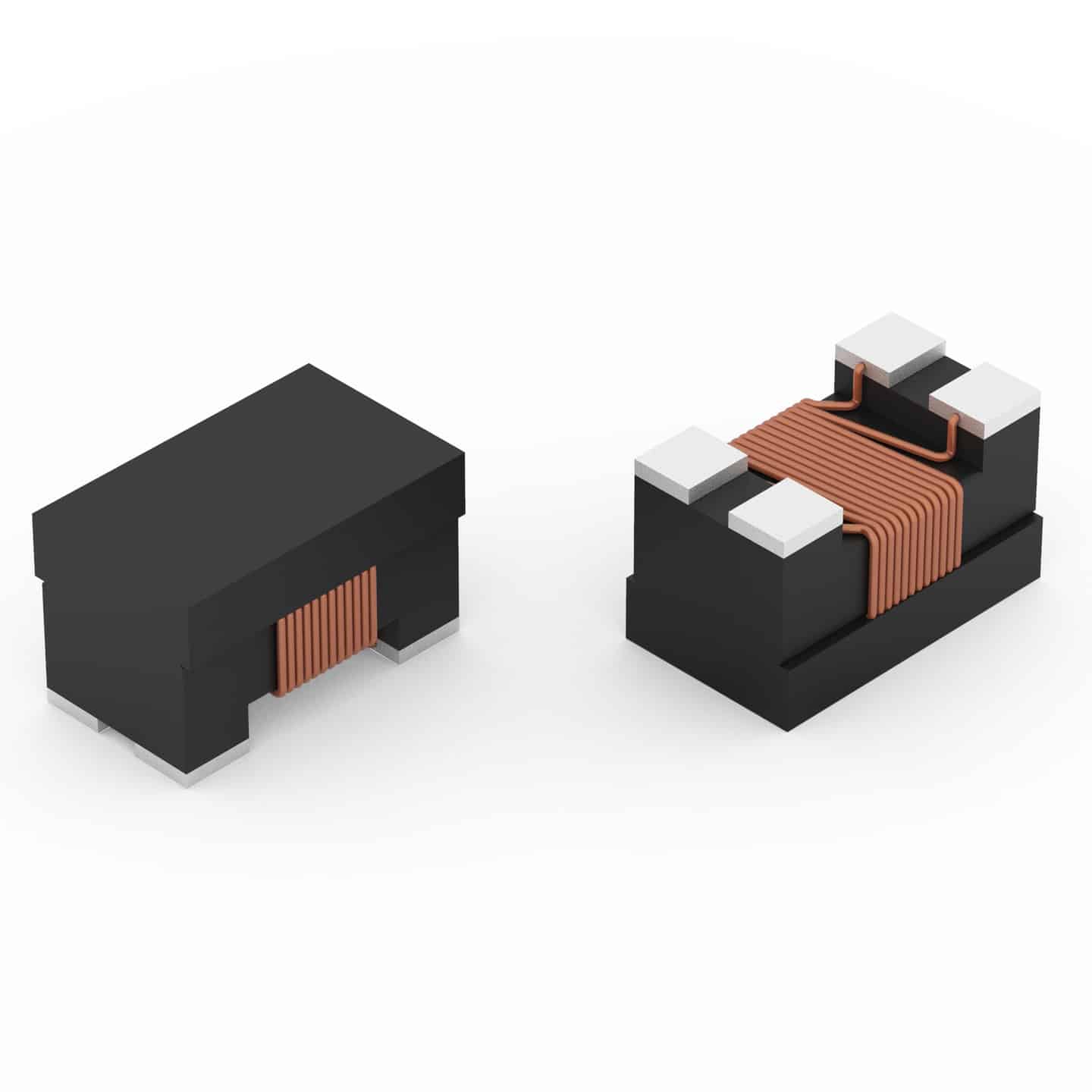
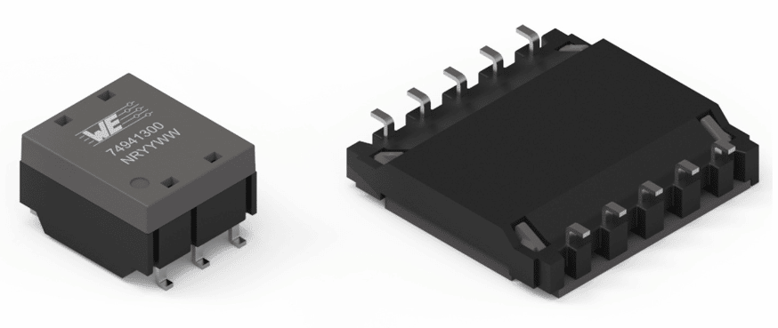
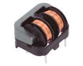
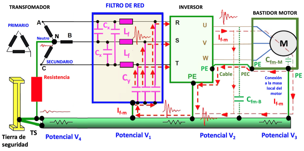
Today, most electronic equipment uses switching power supplies to be powered from the mains. To avoid excessive conducted emissions towards the network, it is necessary to design a network filter with sufficient attenuation. In the basic structure of a network filter, at least one common mode choke is always used. Common mode chokes are inductors specifically designed to attenuate common mode electromagnetic interference (EMI). When the chokes are placed on power lines, they absorb a substantial portion of the kHz to MHz interference, without affecting the transfer of power from AC or DC power lines. The use of a common mode choke in the network filters is recommended and the use of different types of magnetic materials such as MnZn or NiZn as the most common in their core.
Usually, when the noise generated is in the area higher than 1 MHz, the correct material is NiZn. If the generated noise is below 1 MHz, the correct material is MnZn. In common mode chokes, the differential mode is also important due to imperfections in the symmetry of the windings. This article compares four types of magnetic material at the core of the common mode shock. To do this, the conducted emissions of a load consisting of a filament bulb (resistive load) are measured with a triac regulator that acts as an interference generator.
network filter
In the design of a network filter it is important to decide its structure, the values of its components, the design of the printed circuit and the material of the choke core in common mode. Filter attenuation as a function of frequency does not only depend on component values. It also depends on the type of dielectric and construction of the capacitors and, in the common mode choke, on the material of the core and its construction. Figure 1 presents the schematic of a basic network filter with two Y type capacitors (Cy), two X type capacitors (Cx), a resistor (R) and a common mode choke (L1-L2). It is desired to compare the behavior of four types of magnetic materials. For this, four filters have been assembled with capacitors Cx = 680 nF, capacitors Cy = 2,2 nF and L1=L2 = 1 mH, except in the NiZn choke that has a limitation in the inductance value. In this case a value of only 110 μH has been selected. The resistor is only used to discharge the capacitors for safety reasons. Thus, the common mode chokes of the manufacturer Würth Elektronik mounted on each of the filters are: • Filter 1 = 1 mH, ref. WE-CMBNC 744 801 2501, core made of nanocrystalline material
- Filter 2 = 1 mH , ref. WE-ExB 744 844 102, MnZn core + NiZn core
- Filter 3 = 1 mH , ref. WE-CMB 744 822 301, MnZn core
- Filter 4 = 110 μH , ref. WE-CMBNiZn 744 842 311, NiZn core
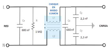
Figure 1. Scheme of the network filter with the same values for R, Cx , Cy. Values of L1 = L2 of the shocks in
common mode from manufacturer Würth Elektronik for:
Filter 1 = 1 mH , ref. WE-CMBNC 744 801 2501, core made of nanocrystalline material
Filter 2 = 1 mH , ref. WE-ExB 744 844 102, MnZn core + NiZn core
Filter 3 = 1 mH , ref. WE-CMB 744 822 301, MnZn core
Filter 4 = 110 μH , ref. WE-CMBNiZn 744 842 311, NiZn core
Comparison of core materials
In filter 1, we have a Würth Elektronik WE-CMBNC choke made of nanocrystalline material. The WE-CMBNC family of chokes use nanocrystalline cores and feature broadband attenuation. Compared to conventional cores, made from other materials such as MnZn, nanocrystalline cores have 20 times more permeability. EMI through the network can therefore be reduced in the low-frequency (kHz) range, where conventional NiZn and MnZn cores have little attenuation. Even in high frequency ranges, high levels of attenuation can be achieved due to the low parasitic capacitance of the windings. Compared to conventional nuclei, the Curie temperature is about three times higher, so it has fewer saturation problems. The very high permeability nanocrystalline core makes it easy to have high and stable inductance values at high temperatures.
It is useful for high currents and good broadband EMI suppression, with a frequency range of 1 kHz to 300 MHz. It is relatively small in size. The most typical applications are: power electronics, input and output filters of AC and DC power lines, EMI suppression in motors and EMI suppression in common mode. In filter 2, we have a dual-core Würth Elektronik WE-ExB choke: MnZn core and NiZn core together. Their insertion losses have a wider frequency range than with a single NiZn or MnZn core. Compared to compensated chokes, it offers 70% higher insertion loss in the low frequency range (150 kHz to 4 MHz) and 30% higher insertion loss in the high frequency range (4 MHz to 30 MHz). 100MHz). This common mode choke is particularly suitable for obtaining good EMI suppression over a wide frequency range (100 KHz to XNUMX MHz). It is good for having good filtering of conducted emissions and also for passing fast transient (EFT) immunity tests. Its typical applications are: EMC filters, network filters, power electronics, EMI suppression in motors and common mode filters.
In filter 3, we have a MnZn material core Würth Elektronik WE-CMB choke, good for high asymmetric EMI suppression. It has a wide band due to the low parasitic capacity winding technique. Withstands high current with small sizes. Applications are: power electronics, power line input and output filtering, filtering of devices without a stable ground connection, EMI suppression in motors, and common mode EMI suppression. In filter 4, we have a Würth Elektronik WE-CMBNiZn choke core with NiZn material. As a nickel-zinc material, it can achieve high asymmetric interference suppression rates at high and medium frequencies. It has high stability against EMI and bursts. And noise suppression up to 300 MHz. Typical applications are: power electronics, power line input and output filter optimized for burst signals.
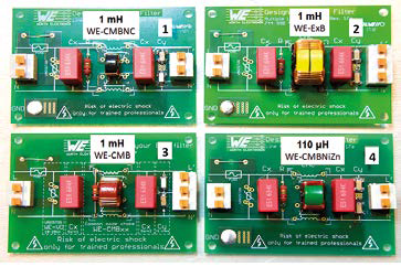
Figure 2. The four filters with the four chokes in common mode with different magnetic material in the core.
The attenuation of each shock
To compare the attenuation of each shock as a function of the frequency of the four selected shocks, let's look at the attenuation curves for each of them. Figure 3 shows the attenuation curve of the 1 mH shock, WE-CMBNC with core of nanocrystalline material. If we loosely set the same 15 dB limit on the graph for comparison, we see that this choke has a frequency range of 200 kHz to 200 MHz, with a maximum at 25 MHz on the common mode attenuation curve. The differential mode attenuation curve is between 50 and 450 MHz, with a maximum at 200 MHz. Figure 4 shows the attenuation effect of joining two cores of different materials (MnZn + NiZn), sharing the two choke windings. . An overlapping effect is appreciated, obtaining an extension of the frequency range. Figure 5 shows the attenuation curve of the 1 mH shock, ExB, with MnZn plus NiZn dual core For comparison we set the same 15 dB limit on the graph. We see that this choke has a frequency range of 80 kHz to 50 MHz with a maximum at 2 MHz on the common mode attenuation curve. The differential mode attenuation curve is between 4,2 and 140 MHz, with a maximum at 20 MHz. Figure 6 shows the attenuation curve of the 1 mH choke, WECMB, with MnZn core core. For comparison we set the same 15 dB limit on the graph. We see that this choke has a frequency range of 80 kHz to 70 MHz with a maximum at 1,8 MHz on the common mode attenuation curve. The differential mode attenuation curve is between 18 and 100 MHz, with a maximum at 45 MHz. Figure 7 shows the attenuation curve of the 110 μH shock, WE-CMBNiZn, with NiZn core core. For comparison we set the same 15 dB limit on the graph. We see that this choke has a frequency range of 590 kHz to 150 MHz with a maximum at 1,8 MHz on the common mode attenuation curve. The attenuation curve in differential mode is between 16 and 260 MHz, with a maximum at 71 MHz. To have a better visibility of the comparison, figure 8 shows a graph that summarizes the frequency parameters of the four cores, both in common mode as in differential mode. The final results of the conducted emission measurements also depend on the structure of the filter scheme and on the values of the capacitors Cx and Cy, as stated at the beginning.
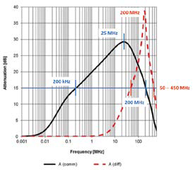
Figure 3. Filter 1 = 1 mH , ref. Würth Elektronik WE-CMBNC 744 801 2501 , core made of nanocrystalline material.
Conducted Emissions Measurements
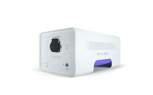
To carry out the measurements, the same charge formed by a filament bulb controlled with a phase regulator with triac is applied to the four filters (figure 9(a)). The element that actually generates the noise is the regulator. The regulator is inexpensive, with an internal filter with little attenuation, insufficient to be able to correctly pass the CISPR32 standard. Therefore, adding an external filter adds attenuation to the internal filter and contributes to having conducted emissions below the limits of the standard. To measure conducted emissions, a Line Impedance Stabilization Network (LISN) is used. The LISN used is shown in Figure 9(b). Conducted emission measurements are made in the frequency range of 150 kHz – 30 MHz, according to CISPR 32, with the limits allowed for a domestic product (Class B). Figure 10 shows the spectrum analyzer used, with the four filters to be compared in front. Although the network filter can also affect radiated emissions from 30 MHz, together with other aspects of the design such as the cabling, the level of shielding of the equipment enclosure, etc., to focus the problem, in the comparison here proposal we are going to focus on the conducted emissions between 150 kHz and 30 MHz. The conducted emissions have been carried out outside a Faraday cage, in an electromagnetically calm environment. For this reason, it is convenient to first make sure that the background noise is sufficiently low and is far from the limit established by the standard.
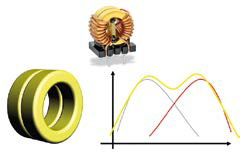
Figure 4. Filter 2: Double core, WE-ExB series: MnZn core + NiZn core.
In figure 11, the measure in blue color is the background noise. The same figure shows the measurement of the conducted emissions from the regulator without the external filter, with the filament bulb loaded and with the control in a fixed reference position, untouchable during the entire measurement process of the four external filters. The limits of the CISPR32 standard, class B, shown in the figures that present the measurements are: 150 – 500 kHz, 66 dBμV decreasing linearly with the logarithm of the frequency up to 56 dBμV, 500 kHz – 5 MHz, 56 dBμV and 5 MHz – 30 MHz, 60 dBμV. As can be seen, the noise generated by the regulator exceeds the limit in several peaks below 200 kHz and in other peaks between 800 kHz and 1 MHz, with an emission level bordering on the limit in the range between 150 kHz and 1 MHz. It would be convenient to have a level of emissions with a minimum of 5 dB below the limit and it would be advisable to have a minimum of 10 dB below the limit. In these circumstances, it is evident the need to add an external filter to obtain more attenuation, in order to follow the previous recommendation.

Figure 5. Filter 2 = 1 mH , ref. Wurth Elektronik WE-ExB 744 844 102, core
of MnZn + NiZn core.

Figure 6. Filter 3 = 1 mH , ref. Wurth Elektronik WE-CMB 744 822 301, core
of MnZn.

Figure 7. Filter 4: 110 μH, ref. Wurth Elektronik WE-CMBNiZn 744 842 311,
NiZn core.

Figure 8. Comparison of frequency margins of each shock in common mode.

Figure 9. (a) load formed by a filament bulb controlled with a triac regulator
(b) Line Impedance Stabilization Network (LISN)

The results of the emission measurements of the filters
Figures 12 to 15 show the results of the measurements of the conducted emissions from the regulator with each of the four filters. All four filters clearly provide enough attenuation to comply with CISPR32. Over the entire frequency range, all four filters meet the proposed recommendation to have noise a minimum of 10 dB below the cutoff. In the four filters, a set of emissions is measured between 5 MHz and 25 MHz, which has a maximum of 30-32 dBμV, with enough difference to reach the limit (a difference of about 28-30 dB). In filter 1, in figure 12, at 200 kHz the peak is 15 dB below the limit, complying with the 10 dB recommendation. In filter 2, in figure 13, at 150 kHz the peak is 33 dB below the limit. In filter 3, in figure 14, at 150 kHz the peak is 29 dB below the limit. Finally, in filter 4, in figure 15, at 230 kHz, the peak is 27 dB below the limit. Comparing the results, the best filter is filter 2 with the dual-core crash. Filter 4, despite only having a 110 μH choke, has good results. It is evident that each filter must be adapted to the type of noise that needs to be attenuated. An equal set of filter design rules cannot be applied to all types of EMI. Each type of EMI needs to be analyzed and the filter suitably adapted in values and materials. The end of the design process should always end with some measurements to verify that the results are adequate so as not to exceed the limits of the standards.
Conclusion
Four types of materials have been compared in four common-mode choke nuclei, respectively keeping the values of the capacitors Cx and Cy the same. The results of the measurements of the conducted emissions of the four filters have been presented. Although it is true that each material presents greater effectiveness in a different frequency range, these differences are not entirely appreciable in the measurements made. We must consider that these filters have been compared with a triac phase regulator, a very characteristic type of noise generator that generates a spectrum where the harmonics of a fundamental frequency can be seen. We know that by attacking this fundamental frequency we will attenuate its harmonics. Therefore, for a more detailed characterization of the bandwidths, the noise source could be changed to a white noise source, whose emissions are uniform at all frequencies.
Acknowledgements I appreciate all the help received in the form of documentation, components and advice from Würth Elektronik, especially Juan Miguel del Pino, FAE (Field Applications Engineer) at Würth Elektronik Spain and Ismael Molina, PM (Product Manager) at Würth Elektronik Germany. Without this help, this article could not have been written.

Figure 10. Spectrum analyzer with the four filters in front.

Figure 11. Measurement of the conducted emissions of the regulator with the internal filter
original. Class B limits. Background noise in blue.

Figure 12. Filter results 1 mH, CMBNC, core of nanocrystalline material.

Figure 13. Results filter 2, 1 mH, ExB, MnZn + NiZn core.

Figure 14. Results filter 3, 1 mH, CMB, MnZn core.

Figure 15. Filter 4 results, 110 μH, CMBNiZn, NiZn core.


