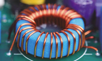
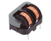
Despite the widespread use of digital circuitry, such as processors, programmable logic circuits, and SoCs that are their combination, the electronics builder often has to use “analog” items, such as resistors, capacitors, or inductors. Interestingly, while it is relatively easy to make a resistor or capacitor (with a capacity on the order of picofarads) in an integrated circuit frame, it is very difficult to make a coil. For this reason, many components still include an inductor that is connected as an external component in the application notes. The article provides basic information about coils and describes their construction elements that affect the parameters.
CONSTRUCTION OF AN INDUCTION COIL
induction coil it is not a complicated element. It consists of a core and insulated conductive coils wrapped around it. The coil core may be suspended in air or made of magnetic materials. It is important that the coils wrapped around the core are insulated, therefore either insulated wire is used to make the coils or they are wound with a non-insulated wire (for example, so-called silver wire), but with an appropriate air gap that ensure the required separation of the coil from the coil. If the coil is wound with non-insulated wire, the coil of the coil is shorted, and yes, it will have some inductance, but definitely different than expected.
Often in practice, as a result of exceeding the allowable temperature or voltage, the induction coil is damaged, which consists in a short circuit between the windings due to the breakdown of the insulation of the wire of the winding. Such a damaged induction coil must be rewound or replaced with a new one. Mains transformers are often damaged in this way. Further use of such a damaged transformer can lead to its overheating, a short circuit in the electrical network, or even ignition of the transformer itself or the device supplied with it.
WHAT IS AN INDUCTION COIL?
induction coil It is an element that stores energy in the nucleus in the form of a magnetic field, and thus converts the energy of the electric current into energy of the magnetic field or vice versa. The change in current flowing through the windings generates an electromotive force in the direction that counteracts this change. Similarly, an alternating magnetic field penetrating the core induces a voltage. With the help of the formula, it can be expressed as follows:

In this formula:
- e – is the electromotive force (voltage in volts) produced by the coil
- dϕ / dt \ – is the change in magnetic flux over time,
- di/dt \ – is the change in current over time,
- L\ – is the coil parameter called inductance; his unit is Henr.
It is easy to notice the characteristic mentioned above - the electromotive force e has the opposite direction to the voltage that causes current to flow. This counteracts sudden changes in the current flowing through the coil and leads to one of its basic applications: the use of an inductor such as the so-called stuffing box.
INDUCTION COIL – BASIC PARAMETERS
The basic parameters of a coil are its inductance and resonant frequency. Inductance is the ability of a coil to store energy in the form of a magnetic field caused by current flow. Inductance is measured in Henrach and is expressed as the ratio of instantaneous voltage to current change over time.


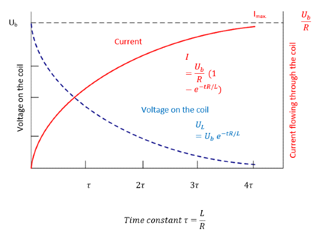
Plots of current and voltage drop across the terminals of an inductor. The drop is greatest at power up and decreases over time. This drop counteracts the increase in current and therefore the amperage is at its lowest when power is applied and increases with time. It is often said that the voltage in the coil is ahead of the current.
The above figure shows what happens to the coil voltage and the current flowing through it when a voltage source is connected to its terminals. The solid red line shows the current flow. As can be seen, the current increases from the moment the source is connected until the maximum value defined by Ohm's law is reached, that is, the relationship between the terminal voltage and the resistance of the source. coil. The dashed blue line shows the voltage drop across the coil. As can be seen, this drop is greater at power-up and less after the current has reached its maximum value. This is due to the fact that the induction voltage is in the opposite direction to that applied to the terminals.
The coil resonant frequency was written when discussing non-ideal coil parameters, because it is related to parasitic capacitance.
Core material and relative magnetic permeability
The core is a very important element of the induction coil. The core is characterized by the type of material used and the relative magnetic permeability associated with it. Relative, since it is determined in relation to the permeability to vacuum. It is a dimensionless number defined as the ratio between the magnetic permeability (absolute μ ) of a given medium and the magnetic permeability of the vacuum μ0.
By definition, magnetic permeability is a quantity that determines the ability of a given material or medium to change magnetic induction when the magnetic field strength changes. Otherwise, it can also be said that permeability is a property of a material or medium that determines its ability to concentrate magnetic field lines. The magnetic permeability of vacuum according to data published in 2002 by the Data Committee for Science and Technology (CODATA) is a scalar marked with the symbol μ0 and whose SI value is μ0 = 4·Π·10-7= okolo 12,566370614 10-7 [H/m = V s/A m].
The inductance of the coil is expressed by the formula:

In the formula, the individual symbols mean:
- L – Henrach inductance,
- μ 0 – magnetic permeability of the vacuum,
- μ\ – relative permeability of the core material,
- Z\ – number of coil turns,
- S\ – cross-sectional area of the coil,
- l – coil length.
The relative permeability of uncontaminated air does not differ much from the permeability of a vacuum, so for the sake of simplicity in engineering practice it is assumed that μ = 1 and the formula for the inductance of the air coil takes the form:

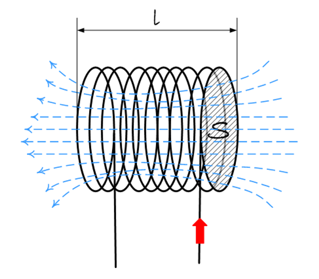
The lines of force of the magnetic field with the direction that complies with the Lentz rule (the so-called "right-hand rule") are drawn in blue").
In terms of their magnetic properties, materials are divided into paramagnets (which become magnets when placed in a magnetic field), ferromagnets (which become magnetized in the presence of a magnetic field), and diamagnets (which weaken the magnetic field). The type of core material greatly influences the coil parameters. There are no particles in a perfect vacuum that can affect the induction dependence on the magnetic field strength. Therefore, in each material medium the inductance formula will be modified due to the presence of the magnetic permeability of this medium. For a vacuum the relative permeability is exactly 1. For paramagnets the relative permeability is not much greater than 1, for diamagnets it is slightly less than one; for both media types the difference is so small that in technical applications it is often neglected to assume the value equal to 1 .
Let's summarize this paragraph by listing the coil parameters that have the biggest impact on its inductance:
- The inductance of the coil increases with:
- number of turns,
- the relative permeability of the core material,
- coil Surface,
- decrease in coil length.
- The inductance of the coil decreases when:
- the number of turns is reduced,
- the relative permeability of the core material decreases,
- the surface decreases,
- increases the length of the coil.
What are the cores used for? The first reason is that more energy can be stored with fewer turns than the air core equivalent. The second is the mechanical structure of the coil: the core provides the skeleton for the coils and their mounting on the target device. The third important reason is the concentration and conduction of the magnetic field. In some applications it will also be important to be able to adjust the inductance of the coil by changing the position of the core in relation to the turns, for example by sliding it in or out.
IMPERFECT COIL
So far, we have considered the parameters of an ideal coil. Meanwhile, under real conditions, the winding wire will have a certain resistance and capacitance, which will affect the actual parameters of the coil, which we have not yet considered. The figure shows the equivalent DC diagram of a real coil. A resistor representing the resistance of the wire winding is connected in series with the turns. As current flows through the coil, it will not only cause a voltage drop, but also power loss in the form of heat, which can cause the coil to heat up and change core parameters. As a consequence, the energy efficiency of the entire device also decreases.

Equivalent schematic diagram of a coil for DC analysis
When analyzing alternating current, one must also take into account the parasitic capacitance created by the insulated layers of the conductor, and therefore in the surrogate diagram, in addition to the resistance, there is also a capacitor connected in parallel to the coil terminals. . This creates a resonant RLC circuit, with the coil itself being inductive before the resonant frequency is reached and capacitive when it is reached. Therefore, the coil impedance increases at the resonant frequency to reach the maximum value at resonance and decreases when it exceeds it.
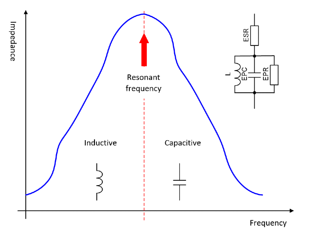
The change of the nature of the actual coil after reaching the resonant frequency. Markings on the equivalent diagram: L – inductance, EPC – stray capacitance, EPR – parallel resistance symbolizing power losses, ESR – series resistance symbolizing the resistance of the wound wire)
Three types of power losses in inductors.
There are three dominant types of power loss in coil applications. The first is the series resistance loss mentioned above, that is, the resistance of the winding lead. This power loss must be taken into account especially when the current through the coil is high. Most of the time we deal with it in power supplies and power circuits. This type of loss causes the coil and, consequently, the entire device to heat up. It is also the most common cause of failure, as high temperatures can damage insulation and short out coils.
The second type of energy loss is core loss. They appear as a result of irregular operation of the core, eddy currents and changes in the position of the magnetic domains. These losses are dominant when the current through the coil is low. They can be found in high-frequency circuits, digital signal splitters, and others. It does not cause so much coil damage as problems with loss of signal level in sensitive circuits.
The third type of power loss is magnetic flux loss that can be dissipated by mechanical fasteners, air gaps in the core, or the coil itself.
TO END
An inductor is a simple component and therefore perhaps a bit sloppy. Meanwhile, when building an electronic circuit equipped with inductors or transformers, special attention should be paid to the selected inductive components, including their resonant frequencies and core material parameters. Different cores are used at a current frequency of tens or hundreds of hertz, and others are used at hundreds of megahertz and more. Sometimes, with high-frequency signals, a section of cable with a threaded ferrite bead is sufficient.
Inductors can be made in various ways. Typically several to several hundred turns of wire are wound on the core. In some applications, the turns are made in the form of traces on the circuit board, sometimes encasing them in a ferrite cup. Today most coils, especially coils used in power circuits are made for SMD mounting. At the same time, the technological race continues and new magnetic materials are constantly being developed, which retain their properties despite the increase in temperature, have lower losses, etc.
A coil designed for low-frequency operation generally has an iron core and a large number of turns, and is therefore relatively heavy. Therefore, in many applications, especially those exposed to shocks and impacts, the method of mounting is of great importance. Soldering the coil is usually not enough - its core needs to be more securely fixed with a clamp, handles or screws. When choosing a coil or transformer for the device, it is worth taking this into account.
THE USE OF COILS IN ELECTRONICS
Coils are used for:
- blocking the flow of alternating current in the circuit,
- short circuit current (voltage),
- measurement of the passage of time based on the disappearance of the current flow,
- construction of oscillating circuits,
- construction of filters for specific frequencies,
- coupling of amplifier stages,
- decrease or increase voltage.
Some coil applications are similar to capacitor applications. As we already know, the coil behaves like a capacitor when it exceeds the resonant frequency. However, it does not mean that these elements can be used interchangeably in the system. We encourage you to watch the video dedicated to the subject of inductors and their application in electronics:


