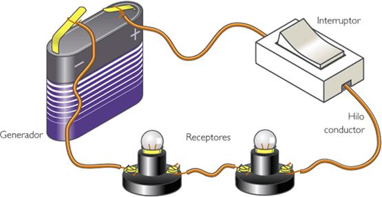
Un electrical circuit It is the set of electrical elements connected to each other that allow the production, transport and use of electrical energy with the purpose of converting it into another type of energy such as, for example, heat energy (stove), light energy (light bulb) or mechanical energy. (engine). The elements of a electrical circuit used to achieve this are:
- Generator: A part of the circuit where electricity is generated, sustaining a voltage difference between its ends.
- Driver: Thread through which the electrons driven by the generator circulate.
- Electric resistance: They are elements of the circuit that oppose the passage of electric current.
- Light switch: Element that allows the passage of electric current to be opened or closed. If the switch is open, electrons do not circulate and if it is closed, they allow their passage.
Resistances of electrical conductors
The resistance is the opposition that the electric current finds to pass through the materials and this depends on three factors:
1. The genre of material. Each material has a different resistance and its own characteristics, with materials being more conductive than others. This resistance is called resistivity [ρ] and has a constant value. [Ω•m] is measured.
two. The length. The greater the length of the conductor, the more resistance it offers. It is measured in meters [m].
three. The section. The larger the section, the less resistance the conductor offers. It is measured in [m2].
The resistance of a conductor is measured in ohms (Ω).
Interpretation of the color code of a resistor
Commercial resistors (those that are used to practice electrical circuits) have 4 painted rings that serve to identify their value.
The first ring corresponds to the first number; the second, to the second figure; the third - to the number of zeros, and the fourth ring - to the tolerance limit of the resistor. The resistor color code is as follows:
Interpretation of the color code of a resistor
Commercial resistors (those that are used to practice electrical circuits) have four painted rings that serve to identify their value.
The first ring corresponds to the first number; the second, to the second figure; the third - to the number of zeros, and the fourth ring - to the tolerance limit of the resistor.
two. parallel association. Branches are created in the circuit. The electrical current that leaves the generator has different paths to travel. For example, in case of having 4 resistances associated in parallel, the equivalent resistance of the circuit.
Each and every one of the components of an electrical circuit are graphically represented through elementary symbols accepted by international standards. Electrical circuit schematics are simplified drawings used to quickly and clearly see how circuits are connected.
Ohm's Law
Ohm's Law, promoted in XNUMX by the German mathematician and physicist Georg Simon Ohm, is one of the fundamental laws of electrodynamics. It is used to determine the relationship between potential difference, current intensity and resistance.
Ohm's law says: "in an electrical circuit, the intensity of the current that runs through it is directly proportional to the applied voltage and inversely proportional to the resistance that it presents". His formula is as follows:
Joule's Law
Joule's law shows the relationship between the heat generated by an electric current flowing through a conductor, the current itself, the resistance of the conductor, and the time the current is flowing. This law is named after the British physicist James Prescott Joule, who in 1845 showed that heat is:
- Proportional to the time over which the electric current passes.
- Proportional to the square of the circulating intensity.
- Proportional to the resistance of the conductor.
The Joule effect limits the electric current that the cables of the electrical conductions can carry.


