1. Introduction
For more than 20 years, most industrial plants have used transmitters to be able to send information from the field to the Control Room.
We can find transmitters of the fundamental variables as presión, temperature, flow and level. As well as non-fundamental measurements such as pH, Density or the speed of rotation of a motor.
These transmitters allow the process signal to be encoded and scaled so that it can be transmitted to the control system. This type of measurement and communication is a standard within the process industry.
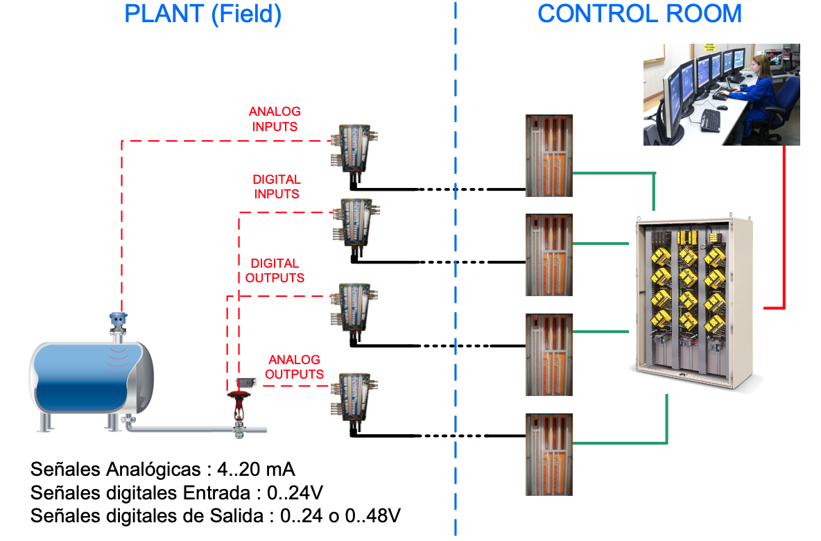
The transmitters are installed where the measurement is required and are connected, most often through a pair of conductors, to a Field Box (junction box) where the signals are normally grouped by type (analog input, analog input, output, digital input or digital output) to be connected through a poly-cable to the Technical Room and later sent to the Control Room.
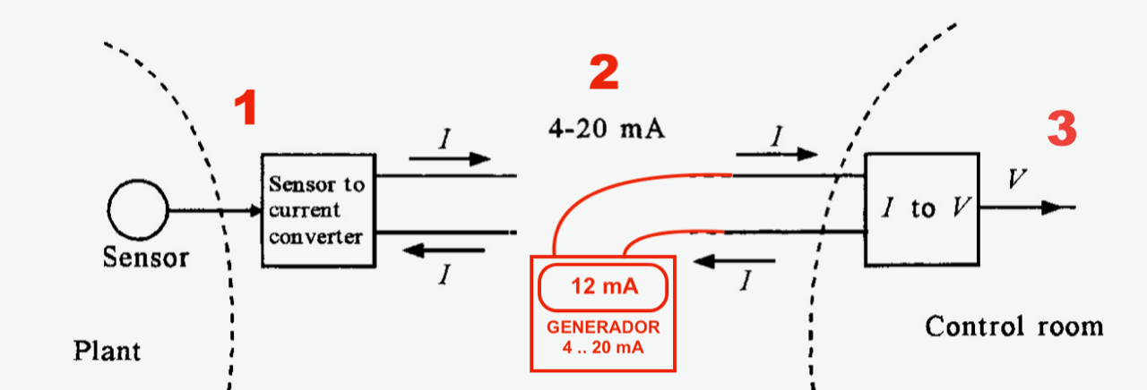
Three different types of scales are involved in this process. Next we have our reference chart of this article. The first scale (1) corresponds to the process measurement, for example 0 to 5 bars in the case of a pressure measurement. The second scale (2) corresponds to the current loop scale, typically 4 to 20 mA. And the third scale (3) corresponds to the signal displayed on the screen, for example a scale from 0 to 100%.
There may be additional scales, such as the one used by the input card to the control system that converts the analog signal into digital. But I have preferred to leave this scale aside because it does not provide additional information for this article.
2. Who does this work? – The Instrumentation Technician
One of the usual tasks of the construction and/or maintenance team is to adjust and check the range of a new instrument to adapt it to what is required by its corresponding specification. This process is carried out regularly by both teams. To carry out this operation it is necessary to understand the operation of a current loop communication and how a control system works.
Usually those responsible for carrying out this work have received specialized training in different topics such as
- P&D diagrams – used to be able to locate the instrument in the Plant and to know the type of technology and the type of communication with the Technical Room.
- Process control theory
- Analog and Digital Control
- Microprocessors
- Operation and maintenance of industrial communications
An instrumentation technician performs calibration, documents, checks current loop status, troubleshoots, and repairs or replaces instrumentation and associated equipment.
3. What does the job consist of?
Modifying the working range of an instrument involves modifying the instrument's measurement scale. With this operation we modify the response of the instrument to changes in the process. In the attached example we can see the diagram of a process measurement where we have a Sensor that reacts to an applied pressure of 100 PSI generating an analog signal that is sent to the ADC converter.
Once converted into digital, this signal is sent to the microprocessor where it will be scaled according to the upper (URV) and lower (LRV) ranges, defined by the instrument technician.
The scaled and normalized signal is sent to the DAC output converter to convert it into a 4 to 20 mA signal and send it to the Technical Room.
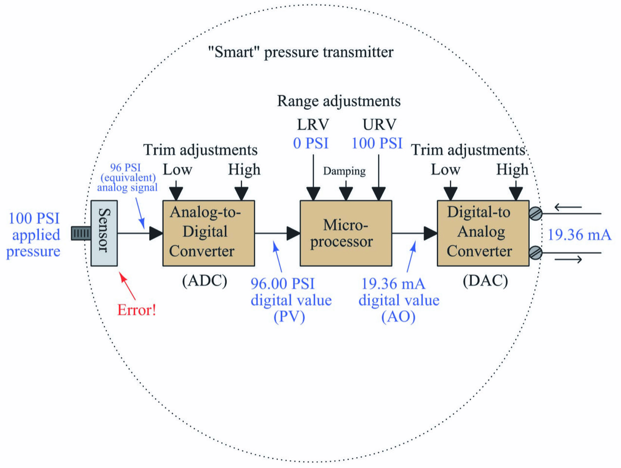
The example shown is a pressure instrument with a measurement range of 0 to 100 PSI and with a measurement error of 4 PSI.
Normally the adjustment of the working range for a new instrument is carried out by the supplier, to whom, through the requisition sheet, we will have indicated what the working range of the instrument will be.
Ideally, after changing the working range we should perform a calibration of the instrument. Calibration allows us to check that parameters such as sensitivity, response time, and instrument precision are sufficient for the new working range.
3.1 What is calibration?
Calibration consists of comparing the measurement result of an instrument with the result of a known measurement or pattern. Usually the precision of the pattern will be higher than that of the instrument that we want to calibrate.
As a general rule, new instruments are checked on the calibration bench to detect possible measurement deviations suffered during the transport of the instrument.
When the instrument is purchased calibrated, it is necessary to request a calibration certificate from the supplier and file the document properly.
Once we are certain that the instrument measures correctly, we will proceed to install it in the plant.
In the case of an existing instrument, that is, an instrument that has been in service for a few years, in order to calibrate it, it must be disassembled and taken to the calibration bench. In this case, the main motivation for performing a calibration may be:
- There has been a change in the process conditions and the calibration range is no longer valid and must be adapted.
- The instrument presents a drift caused by the conditions of the instrument's installation environment, power supply, having added elements within the current loop...
- The instrument is subject to control either because the measure belongs to the group of instruments of Quality, Environmental control or Industrial Process Safety.
The calibration process may involve modifying scales 1 and 2 of our reference chart.

Once we have installed the equipment or instrument in the plant, either for the first time or because we have replaced or re-calibrated it, it is necessary to check the loop.
3.2 What is the loop check?
The loop check involves technicians in the Field and a technician in the Control Room who supervises and checks the values received in the Control System, also known as Human Machine Interface (HMI).
Sometimes it will be necessary for an additional technician to be in the Technical Room where the Field Inputs and Outputs connect to the Control System terminations.
As a general rule, to check a process signal, the instrument is disconnected from the current loop or loop and a known intensity signal is injected through a portable current generator.
From the Field, using the Loop Diagram as a guide document, the instrument technician or instrumentalist verifies that the loop works correctly by verifying that the commanded state of the device (example: valve open) agrees with the feedback status of the device (example: flow circulating is equivalent to that of the open valve)

To check the entire range of the signal, signals with intensities ranging from 4 to 20 mA are normally injected.

The technician in the Control Room receives the Field signals and confirms that the received value is the same as expected.
The Field technician, in addition to verifying the signal that goes to the Technical Room and the signal that comes from the Technical Room, will check that the device works as ordered (the valve is open) and the status of the labels and protection / conductor insulation.
The loop verification process should not involve modifying any scale of our reference chart.
4. What problems can we find?
"You cannot control what cannot be measured", this applies to the performance assessment of our function (for example, flow control). The performance can be controlled and thus improves the better the flow measurement as a whole.
The following concepts must be taken into account when installing a new instrument or replacing an existing instrument:
- Fluid Properties (Density, Viscosity, Particles, Acidity,…)
- Operating Conditions (Temperature, Pressure, Flow, etc…)
- Type of Measurement (For example absolute, relative or differential pressure…)
- Required Certifications (ATEX, etc…)
- Requirements of Precision, Accuracy, Repeatability, etc…
- Chemical resistance of wetted parts
- Environmental Conditions where is the instrument installed?
- Particularities of the installation
- Communication with the Control System
On the other hand, the verification or modification of parameters of a process instrument requires authorization from the Production department. It is necessary to agree with Production to be able to isolate the measurement and dedicate the necessary human resources to supervise the rest of the process while the instrument tests last.
For example, if we suspect that a pressure transmitter has a design range that is not adequate for a specific measurement, we have 2 possibilities: replace it with another instrument with the range that we assume is adequate (without technical justification) or simulate the process through calculations to test our hypothesis.
The first option is the most direct and if we are right it will mean a considerable improvement. The second option requires a longer execution time because it is necessary to carry out the calculations previously, but it is safer and implies less risk.
From a risk point of view, both options imply a replacement and consequent temporary loss of benefits during installation. However, the first option, the substitution of an instrument without technical justification, may entail not only a greater loss of production, but also a risk to safety and/or the environment.
Understanding the relationship between the different scales present in an analog signal sent to a Control System is a process that requires the skills and knowledge of an instrument technician.
To help improve the understanding of this universal mechanism in process plants, we have created a control loop simulator.
This simulator allows you to modify the different scales of:
- process signal
- current signal
- Signal in the Control System
And observe what would be the implications of adjusting the range in Plant or in the Control System of a simulated signal.

In this way we can, by properly parameterizing the simulator, estimate the necessary changes without risk to Production and without the need to carry out complex calculations.

5. CONCLUSIONS
According to [1], 60% of the loops are not performing the intended function due to problems with the maintenance and adjustment of the valve and/or the transmitter. This means an opportunity for considerable improvement in more than 50% of the existing signals in our Control System.
With increasingly demanding Production plans and the need to carry out more effective interventions (either maintenance or construction), it is necessary to have tools that allow us to improve our productivity and reduce errors.
The control loop simulator has been set up as a laboratory for instrument technicians or engineers where they can test their hypotheses and dynamically visualize the consequences of their results without affecting the production process.
6 References
1.- Harley Jeffery (2005) ISA – Loop Checking : A technician's Guide
7. Acknowledgments
We would like to thank Iñaki Eseberri, editor of the blog, for his collaboration in writing this article. instrumentation and control.


