In any electrical installation, a certain current flows through the protective conductor to earth. This current is normally called leakage current. These current leaks are normally produced through the insulation that surrounds the conductors and through the filters that protect electronic equipment both in offices and in the home itself. What is the problem? In circuits protected by a RCD (Residual Current Device), leakage current can trigger these differential protections intermittently and unnecessarily. In extreme cases, it can cause high voltage on accessible conductive elements and parts.
The causes of leakage currents
The insulation, at an electrical level, presents certain characteristics of resistance and capacity, and consequently currents can flow through it for both reasons. Since the insulation resistivity value is high, the leakage current should be minimal. However, if the insulation has aged or is damaged, its resistance is lower and significant current can flow. Also, longer conductors have higher capacitance, which translates into higher leakage current.
Electronic equipment, for its part, incorporates filters designed to protect against surges and other electrical disturbances. These filters normally incorporate capacitors at the input, which add more capacity to that of the distribution system, thus favoring the increase in leakage currents.
Solutions to minimize the effects of leakage currents
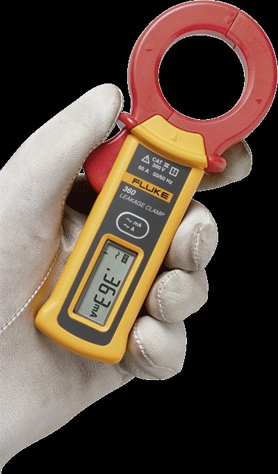
The question is: how can the effects of leakage currents be eliminated or minimized? Quantify the leakage current and then identify the source of the leakage current. One of the methods to do it is by means of an ammeter clamp to measure leakage currents. This instrument, which looks very similar to a clamp meter for measuring load currents, provides high precision when measuring small currents, less than 5 mA. Most clamp meters simply won't register currents that small.
Once the jaw of the current clamp is placed around the conductor, the value of current that it measures will depend on the intensity of the alternating electromagnetic field that surrounds the conductors. To accurately measure small currents, it is essential that the ends of the jaw show no damage or deformation, are kept clean, and fit snugly when the jaw is closed. Be careful not to bend the jaw of the current clamp as this situation can lead to incorrect measurements.
The clamp meter detects the magnetic field surrounding the conductors, for example, a single cable, a shielded cable, a water pipe, etc.; or the pair of cables, phase and neutral, of a single-phase installation; or all active conductors (3 or 4 wires) in a three-phase installation (such as a three-phase RCD or RCD).
When measured on multiple live conductors bundled together, the magnetic fields produced by the charging currents in each conductor cancel each other out. Any unbalance or current difference is a consequence of the leakages that are produced by the conductors to ground or other alternative paths. To measure this current, a leakage current clamp meter should be able to measure currents less than 0,1 mA.
For example, if we measure on a 230 V AC circuit, with all loads disconnected, a leakage value of 0,02 mA (20 µA) can be obtained as a result. This value represents an insulation impedance of:
230 V / (20 x 10-6) = 11,5 MΩ.
(Ohm's Law R=V/I)
If an insulation test is carried out on a disconnected circuit, the result will be around 50 MΩ or higher. This is because the insulation tester uses DC voltage for testing, which does not take into account capacitive effects in the installation. However, the actual value of the insulation impedance would be the current value that would be measured under normal operating conditions.
If the same circuit were measured loaded with office equipment (computers, monitors, photocopiers, etc.), the result would be quite different, due to the capacity of the input filters of these devices. The effect is cumulative, the more equipment that is connected to the installation, the greater the total leakage current, which may be in the order of milliamps. If new equipment is added to a circuit protected by a DCR or differential, this protection could trip at a certain time. As the amount of leakage current varies depending on the operating status of the systems, the RCDs or DCRs could trip randomly, making this type of problem one of the most difficult to diagnose.
A clamp meter will detect and measure a wide range of alternating or variable currents passing through the conductor being tested. When telecommunications equipment is present, the leakage value indicated by the current clamp may be considerably higher than that resulting from the insulation impedance at 50 Hz. This is because telecommunications equipment normally incorporates filters that produce functional currents at ground and other equipment that produces harmonics, etc. The characteristic leakage at 50 Hz can only be measured using a current clamp that incorporates a narrow-width bandpass filter, in order to eliminate currents at other frequencies.
Earth leakage current measurement
When the loads are connected, the measured leakage current also includes the leakage currents in the connected equipment itself. If the leakage current is acceptably low with the load connected, the leakage current from the facility wiring will be even lower.
If it is necessary to measure only the leakage current of the installation wiring, disconnect the load.
Check single phase circuits simultaneously clamping the phase and neutral conductors. The measured value will reflect any current flowing to ground. (Figure 1)
Check three-phase circuits encircling all the three-phase conductors with the clamp. If the neutral is available, the clamp must also clamp it together with the rest of the phase conductors. The measured value will reflect any current flowing to ground. (Figure 2)
Leakage current measurement through the earth conductor
To measure the total leakage current flowing through a particular ground, place the clamp around the ground conductor. (Figure 3)
Measurement of leakage current to earth through unintended paths to earth.
If phase/neutral/ground are clamped together, leakage current in the outlet or switchboard can be identified through inadvertent paths to ground (such as in a metal switchboard sitting on a concrete base). If there are other electrical ground connections (such as a connection to a water pipe), similar currents can be detected. (Figure 4)
Trace the origin of the leakage current
Carrying out a series of measurements can identify the different leakage currents and their origin. The first measure can be taken in the supply conductors of the switchboard. Next, measurements 2, 3, 4, and 5 are carried out to identify the leakage currents of the different circuits. (Figure 5)
Summary
Leakage current can be an indicator of the effectiveness of conductor insulation.
High levels of leakage current can exist in circuits where electronic equipment with filters is used, which, in turn, can cause voltages that disturb the normal operation of the equipment. It is possible to locate the origin of the leakage currents using a leakage current clamp, which allows us to measure very small currents. To do this we must perform a series of averages following the procedure described above.
If necessary, this will allow you to redistribute the loads in the installation in a more balanced way.


