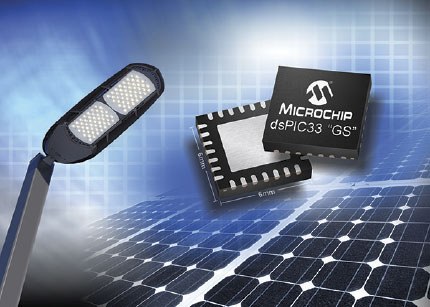
Digital signal controllers add intelligent control and communication to LED lighting, as Charlie Ice of Microchip Technology Inc. explains.
LED lighting is transforming the way lighting is used and opening up new opportunities for designers to add intelligent control and color blending to lighting fixtures.
Digital Signal Controllers (DSCs) can drive innovation in applications ranging from automotive headlights and taillights to the latest lighting shows that can transform a public building into a work of art.
The unique combination of efficiency, dimmability and long operating life allows LEDs to make color changing lighting fixtures more efficient, economical and affordable. The addition of a DSC enables efficient control of the LEDs and precise color control, as well as communication with the outside world.
All of these features give the designer the freedom to develop highly differentiated next-generation LED lighting elements.
Greater brightness and greater complexity
Energy efficient indicator LEDs are part of many products and their simple design is well known to many engineers. All they need is a voltage source and a series resistor of the appropriate value to keep the LED current below a level that is typically less than 5mA. Connecting to the GPIO pin on a microcontroller gives the designer the ability to make the LED blink. However, the simplicity of LED design becomes considerably more complex when daisy chaining high-brightness, high-current LEDs with a forward current greater than 350mA. In this case the designer faces the challenge of controlling the current despite temperature changes and the extreme heat generated by the LEDs themselves.
smart current control
High brightness LEDs need to maintain a relatively high constant current to maintain brightness and color. Figure 1 demonstrates how the luminous flux of the LED is proportional to the forward current (IF) through the LED. Therefore, a constant direct current is essential to achieve consistency of color and light generated.
If a simple resistor is used in series with the LED, the forward current is determined by the following equation:
(IF = (VSource-VF)/R)
As the voltage of the source (VSource) varies, the direct current changes, which produces variations in the amount of light that the LED emits. Therefore, the LED must be connected to a power supply that actively regulates direct current.
Temperature control
As a general rule, the forward voltage (VF) of the LED will increase as the temperature increases, even if the forward current is constant and regulated. Figure 2 shows the variation of an incorrectly regulated forward current as a function of the forward voltage across the LED, and demonstrates why controlling the forward current through the LED is more important than controlling the forward voltage. High power LEDs generate a lot of heat, which can dramatically shorten their operating life and lead to premature failure. The active control of the direct current of the LED allows to determine the level of heat dissipation for each design, based on the desired direct current and the estimated direct voltage. The use of temperature sensors also provides the option of monitoring possible over-temperature situations.
precise color control
The fact that LEDs can change the light they generate almost instantaneously makes them ideal for lighting fixtures that need to quickly change colour. A string of red, green and blue LEDs can be arranged to create any colour, simply by adjusting the brightness of each LED. One method is simply to increase or decrease the forward current of each LED. The problem in this case is that changing the forward voltage not only changes the brightness but also slightly changes the color of the LED, which is a problem in applications that demand accurate color. An alternative is to use a pulsed current that provides the same dimming effect without the color change being perceived. Figure 3 shows a red dotted line representing the mean pulsed current that creates the change in brightness, while maintaining a constant current through the LED so that the perceived color does not change.
digital dimming control
The use of a DSC greatly simplifies dimming using the pulsed current technique. Advanced PWM modules that many DSCs incorporate can be used to generate PWM signals that can be used to drive the LED power stage. These PWM modules offer control inputs that can quickly and accurately turn off the PWM outputs, allowing current to be controlled into the LED to dim it. The dimming level is determined by a number between zero and a value that represents maximum brightness. To set the LED to 50% brightness, a counter would count from zero to 255 and the PWM module would trigger when it reached 128. The PWM output is then turned off to remove current from the LED. When the counter reaches its maximum value of 255, it is reset to 0 and the PWM is reactivated. The process is repeated to create the pulsed current needed to dim the LED, as shown in Figure 4. A frequency greater than 400 Hz is generally used to ensure that the dimming frequency is fast enough to prevent the human eye from being hit. can distinguish the blinking of the LED.
Digital LED Control
In addition to dimming control, a DSC can provide an active power supply to control the direct current that powers a high-brightness LED. Step-up or buck-type switching power supply topologies can be used to power the LEDs, and both can take advantage of the intelligence of the DSC.
A buck topology is used when the forward voltage of the LED or LED string is less than the source voltage. In this topology, shown in Figure 5, the PWM controls the switch (Q) and the voltage across the sense resistor (Rsns) corresponds to the forward current of the LED when the switch (Q) is closed. The DSC comparator is used to compare the voltage across the resistor (Rsns) against a settable internal reference that is proportional to the forward current of the LED. If the sensed voltage is higher than the internal reference, the analog comparator disables the PWM open switch (Q), causing the inductor (L) to discharge its stored current through the diode (D) and LED. At the start of the next PWM period, the switch (Q) is closed and the process starts again.
The advanced features of DSC allow this method to actively regulate the forward current through the LED without resorting to the CPU.
A step-up topology is used when the forward voltage of the LED or string of LEDs is higher than the source voltage, as shown in Figure 6. As in the buck topology, the PWM controls the switch (Q) and the forward current. it is monitored by a sensing resistor (Rsns). The DSC A/D converter module samples the voltage across the sense resistor, which corresponds to the forward current of the LED. This value is then used by a PI (Proportional Integral) control loop, executed by software in the DSC, to adjust the switch duty cycle (Q) depending on the A/D converter reading and a software reference value. corresponding to the required current. By implementing the PI control loop in software, the DSC provides the flexibility for a wide variety of control loop methods. By minimizing CPU usage for the PI control loop the DSC can drive multiple LED strings while still leaving room for other additional functions.
Digital communication
A DSC has sufficient processing power to intelligently control the LED lighting element and also enables a communication protocol to be implemented without the need for a separate communication and control device.
For example, the DMX512 lighting control protocol uses a one-way communication standard, through a master and multiple slaves, to send instructions to individual lighting fixtures at a rate of 512 bytes of data per packet and with individual addressing to each. device or node. The high-speed processing allows a DSP to run the fast control loop, like the PI controller for the boost converter, as top priority, while running the communication protocol, like DMX512, in the background.
Since the communication is implemented by software, it is not limited to a single protocol but allows the lighting element to be controlled with any communication technique.
Shortening of the learning curve
Like any new technology, digital control of LEDs presents designers with a steep learning curve that can be expedited through digitally controlled LED lighting kits, reference designs, and application notes.
These typically include free codes and hardware documentation, and may also offer interchangeable power stages for different topologies. For example, Microchip's DM330014 LED Lighting Development Kit offers LED control daughter cards that allow designers to implement multiple control stages on the same board.
The high efficiency and instant dimming capabilities of LEDs will continue to drive innovation in color mixing and other lighting applications.
By adding the intelligent control and communication that a DSC brings, designers can incorporate advanced features and functionality into LED lighting fixtures that can bring high levels of differentiation and a significant success factor in lighting applications.


