Arduino LCD Display Module Basic Operation
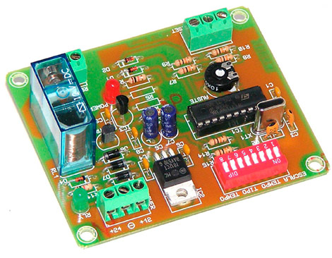
The finished device consists of functional blocks that can often be used multiple times. For example, if we're building a frequency meter with a microcontroller - then, apart from the amplifier block - we'll need pretty much the same components as building a timer. We refer to a microcontroller with an "environment" (resistors, capacitors, quartz and others), screen, buttons and connectors. Of course, the frequency counter won't need a relay to switch the external device and the broadband input amplifier timer, but the core will still be the same. Consequently, the key to self-development of applications is to understand the working principles of the individual functional blocks and then put their functionalities together.
Platforms like Arduino do not require the user to know the principle of operation of the individual components. You can simply connect the main board to the expansion module / cover and run a working application. On the other hand, if we do not have at least a basic knowledge about the components, then in the case of problems with the operation of our device, we are condemned to wander in the dark. Meanwhile, when we look for Arduino components, most of the time we expect a quick effect. It is quite difficult to reconcile such hopes with the need to acquire the appropriate knowledge, since it is enough to enter certain commands to be able to see the first effects on the screen, but to understand why this happened sometimes takes a long time.
Bearing in mind the previously described discrepancies, each of the articles in this series will be divided into 2 parts. In the first, we're going to show you how to achieve the effect. The second part will present how a certain component or solution works.
We will start with the LCD display module, because thanks to it you can see the effect of the work done faster. Now, we will look at other elements of the user interface and then the selected external systems: sensors and actuators. In the meantime, we will also get acquainted with certain programming tricks and methods. And all this based on the Arduino platform, which is cheap, easy to access and, in addition to this, will allow you to use the knowledge acquired to build pre-fabricated devices or their prototypes.
Arduino LCD Character Display Module
The basic interface between the microcontroller and the user typically consists of a display and a button or buttons. As you can easily guess, the former is used to inform the user about the activities of the microcontroller, while the buttons, sometimes replaced by the push button, can be used to enter commands or data. You can find many displays on sale (including ones with a touchpad), but character displays with the HD44780 monitor have become somewhat of an informal standard.
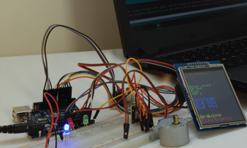
In the first programming example, we will use an Arduino UNO R3 board, a breadboard, a character LCD module with two lines of sixteen characters each, and some connection cables. Of course, this is just a suggestion: the screen can be connected in any way, for example by soldering it to the PCB. Here, the procedure that provides the greatest possibility of altering and changing the design of the connection was used.
If the display module has gold soldered pins, simply connect it to the contact board. Then we connect the screen with the Arduino UNO board, as described in table 1.
| No. of screen contacts | Display signal name | Arduino connector name | Arduino signal name |
|---|---|---|---|
| 1 | VSS | Power | GND |
| 2 | VDD | Power | + 5V |
| 3 | V0 | Power | GND |
| 4 | RS | Analog In | A4 (PC4) |
| 5 | R / W | Power | GND |
| 6 | E | Analog In | A5 (PC5) |
| 7 | DB0 | - | - |
| 8 | DB1 | - | - |
| 9 | DB2 | - | - |
| 10 | DB3 | - | - |
| 11 | DB4 | Analog In | A0 (PC0) |
| 12 | DB5 | Analog In | A1 (PC1) |
| 13 | DB6 | Analog In | A2 (PC2) |
| 14 | DB7 | Analog In | A3 |
| 15 (optional) | LED + | Power | 3.3V |
| 16 (optional) | LED | Power | GND |
Table 1. Connections of the character display with the Arduino UNO board
Remember that for example, having GND connected from the power jack to the header board, you can make connections on the header board and we don't have to connect to the power jack every time.
The use of the connector described as Power is precise because it will provide power to the screen. The Analogi In connector is mounted right next to it, so for convenience it was decided to use the free microcontroller pins. However, don't let the name fool us: digital outputs are required to monitor the display module, not the analog I/O. The connector is called Analog In because it has optional analog inputs, which, however, can also be configured to work in other modes, including digital outputs. And in this way, the analog input A0 is the port PC0, A1 – PC1, etc. (see: ATmega328PU microcontroller cables).
Among the many possibilities of free software drivers for Arduino, a library was chosen to monitor the operation of the LiquidCrystal display. After creating the sketch, we will include it in the first line of the program with an #include directive. With the display connected to the microcontroller as previously described, you can start making your first control sketch of the LCD display module.
We connect the Arduino board to the USB port of our computer. In the Arduino menu, choose File and then New (Ctrl+N). A window similar to the one in Figure 1 will appear. The void keyword tells us that this is where a function will be created that will not return any value. The word void is followed by the name of the function, and the opening closing brace "undefined" marks its end.
When creating a new sketch, the Arduino environment notifies about the need to delimit 2 special functions: a void setup(), which describes the configuration of the microcontroller and contains instructions performed once at the beginning of the program, and void loop() , which contains activities performed in an endless loop.

Why should an application program run in an infinite loop? Windows or Linux applications run under the control of the operating system. If we run the application on Windows, once the work is finished, it returns to the place where it was called and, therefore, more frequently to show the call the desktop, the command line, etc. From that moment, the operating system takes the processor control. The microcontroller on the Arduino UNO board does not have an operating system loaded, so the programmer must ensure that the application shuts down safely. This can be done by powering down the microcontroller (for example, putting it into sleep mode) or by looping instruction execution to avoid executing instructions outside the required memory range. This can be done in the void loop() function or in some other procedure, one instance of which is given below.
Before displaying information on the screen, the microcontroller must be configured. In this scenario, you only need to properly configure the display control outputs.
Early in our sketch, we included a library of display functions:
#include <LiquidCrystal.h>So, for our convenience and readability of the program, using the #define directive we define the names of the pins – outputs of port C of the microcontroller:
//purto PC
#define pc0  A0
#define pc1  A1
#define pc2  A2
#define pc3  A3
#define pc4  A4
#define pc5  A5
Now we notify the microcontroller which pins the display is connected to. To do this, the function lcd() is used, in which the list of reasoning tells the processor where each signal goes. When replacing pins, hold the correct order: LiquidCrystal lcd(RS, Enable, D4, D5, D6, D7). When creating a list of reasoning, we will use Table 1, which contains a list of connections between the Arduino and the LCD module: LiquidCrystal lcd(pc4, pc5, pc0, pc1, pc2, pc3).
Now you need to take care of the configuration of the operation mode of the pins; you must configure them to function as digital outputs. This configuration is saved in the void setup() function:
pinMode(pc0, OUTPUT);
pinMode(pc1, OUTPUT);
pinMode(pc2, OUTPUT);
pinMode(pc3, OUTPUT);
pinMode(pc4, OUTPUT);
pinMode(pc5, OUTPUT);
So we perform screen initialization, setting the number of columns, rows and in the initial step, clearing the screen. After initialization, the LCD screen should be blank, but for safety and convenient working principle, it is worth following this instruction further:
lcd.begin(16, 2);
lcd.clear();
After all, one command is enough to display the message:
lcd.print("Hello!");We don't put any command in the loop() function. After displaying the message, the program will simply "turn" in an endless loop, wasting CPU time. For starters, it would be possible at this point, for example, to enter power saving mode, as the message on the screen would not change anyway, but it would require more hardware research, which is not convenient at this stage. .
The entire program that displays the message "Hello!" can be found in the supplementary materials of this text. If the preceding description and the effect achieved are satisfactory, you may suppress reading the rest of the text. In the next article, we'll cover somewhat more advanced operations on displayed content than just displaying the message.
LCD Display Module Operation
A more detailed analysis of the topic should start by discussing the structure of the microcontroller that is mounted on the Arduino board, but it is a very extensive topic. Therefore, we will first consider how the LCD module works.
Basic knowledge of memory chips and digital chips is usually required to understand how to monitor LCD module. Knowledge of terms such as logic high, logic low, waveform, data, eight-bit, byte, bit, rising, and falling edge is essential. This is necessary because, from the manipulator's perspective, the display module is seen as a kind of digital memory with which the microcontroller can communicate bi-directionally. While, in fact, the LCD display module has its microcontroller (this is the one mentioned at the beginning HD44780 or similar), which not only receives the data to be displayed, but also executes the commands related to the operation of the LCD module. and it is screen compatible. Due to the fact that in the system the microcontroller integrated in the display module has a strictly specialized autonomous function, such systems are often called slaves or slaves. The microcontroller built into the Arduino board performs a superior control function. In general, these systems are called teacher or teacher. We will come across these concepts many times in descriptions of multiple devices connected to the microcontroller.
Logic “0” and “1”
Let's go back to basics for a moment. In CMOS circuits, and most modern integrated circuits are used in such technology, logic "1" is at least ninety-five percent of the supply voltage and logic "0" is either a lower voltage or equal to 0.3 V. If the processor circuit has a built-in power supply, which is often the case with more complex processors, the logic "1" is defined with reference to the internal power supply. It can also be different – if the CMOS system has inputs compatible with TTL levels, then logic "1" is a voltage greater than 4V. Therefore, when in doubt, it is worth consulting the datasheet. of a given system. We can find it easily on the Internet.
Ascending and Descending Slope
A change in logic level causes a change in voltage. This change is generated by excessive steps, but nevertheless, over time. When the level changes from "0" to "1" it is a rising edge, and when it changes from "1" to "0" it is a falling edge. The duration of the transition is called the rise time or the fall time, respectively. Generally, it is a few nanoseconds, but this is not necessarily the case.
In a microcontroller, a single line carrying either level "0" or "1" is called a data bit. eight such lines make a byte. An AVR microcontroller, like the built-in Arduino UNO, has an eight \ -bit data word, so it can process 1-byte words, decimal 0...XNUMX. If the number is greater than XNUMX, you must divide it into "chunks," perform an operation on them, and then flatten the result. However, we should not worry about that, since the Arduino compiler does it in the background. However, you must bear in mind that the more bits a certain variable requires, the more time it will be processed by the microcontroller.
LCD display module control
In this case, the teacher microcontroller controls the LCD display module with output signals. By switching its output signals, it controls the logic levels at the inputs of the display module. Thanks to this, you can choose when to save the data and the memory area in which the data is to be saved:
The logic "1" at the RS (Record Select) input saves the data in the image memory, while the logic "0" – saves the data in the control register of the display module. The teacher microcontroller must be able to supervise this input in order to properly send commands to the display supervisor (RS=0) and data to be displayed (RS=1). Shorting this input to a constant high logic level will prevent the display module from executing "clear screen" type commands and will not allow proper initialization (the control register will not be free).
The logic "1" on the R/W (read/write) input reads the data and the logic "0" writes.
In our example, we permanently force this LCD module input low by connecting it to ground. This is adequate assuming that we are only going to write data to the screen and not read it. By adding this input to the incessant logic level, we lose the ability to read the display's memory and its control register, and therefore the "busy" signal. The "Busy" test speeds up the work of the display module and also allows you to test the accuracy of your supervisor's response to received data, but it also occupies one auxiliary port line of the teacher microcontroller and requires one more connection and complicates programming. service a bit.
The falling edge at the AND Also (Enable) input rewrites the logic levels (consisting of either four- or eight-bit data words) from inputs DB0…DB7 to the internal memory of the LCD module.
When monitoring the operation of the LCD character display module, we have 2 operating modes at our disposal, generally eight-bit and four-bit. In the first, connecting the screen requires at least ten data lines (RS, Y also, D0…D7). From the supervisor's perspective, this mode is very efficient if you can connect a display to the host system as memory on an eight-bit data bus. Display module addressing sets the enable input high, low, or high (depending on whether it is a command or data to teach) to RS, puts the data on the bus, and changes the level to Enable down. In certain systems, the supervisor greatly facilitates this.
In the four-bit perfect mode we still use the eight-bit word, but only the inputs D4…D7 of the display module are connected to the host system, and the eight\-bit data words are divided into 2 portions of four bits each. This complicates the maintenance schedule and does not allow for a simple connection of the display module to the supervisory system, but saves four GPIO lines from the microcontroller.
In simplified LCD module handlers that do not use the R/W lines a priori, it is assumed that the display module is working properly. A certain predetermined time is set, such as the execution of the longest execution command (usually around two milliseconds), and it is assumed that after this time the display has executed the command or displayed a character and next data can be sent . In general, the microcontroller built into the display module is faster: just executing the clear (screen clear) command takes up to two milliseconds. On the other hand, if, as in this case, we have two lines of eight characters on the screen, then it doesn't matter much whether we send sixteen bytes in thirty-two milliseconds or one hundred microseconds. No user is going to be able to appreciate it anyway. This only changes in the case of graphic displays to which a considerably larger amount of data is transmitted.
Arduino doesn't give us much leeway when it comes to monitoring the screen. The ATmega328 microcontroller built into the Arduino UNO has no external address lines, so monitoring the display in eight-bit addressable mode like external memory is out of the question. However, if we use a GPIO port, more to monitor the R/W signal, we can test the busy flag and read the contents of the registers and memory of the LCD module.
The function of the same name, that is, LiquidCrystal(), is used to configure the procedure for attaching the screen in the LiquidCrystal.h library. The way to append the screen is determined by the function that calls the argument list:
LiquidCrystal(rs, enable, d4, d5, d6, d7) – XNUMX-bit interface, no display module, R/W input control, and therefore no data readability.
LiquidCrystal(rs, rw, enable, d4, d5, d6, d7) – Four-bit interface, with control of the R/W input of the LCD module and the ability to read data from the display.
LiquidCrystal(rs, enable, d0, d1, d2, d3, d4, d5, d6, d7) – Eight-bit interface, but cannot read data.
LiquidCrystal(rs, rw, enable, d0, d1, d2, d3, d4, d5, d6, d7) – Eight-bit interface, data intelligible.
The HD44780 supervisor is a universal system, tuned to accept LCD displays with a different number of characters (columns and lines). As a result, after power is turned on, the supervisor "does not know" which display is connected and must be configured for proper operation. In Arduino, the function begin() is used for this, whose rationales are the number of columns and the number of rows. For example, if you have a screen with two lines of sixteen characters, we would call begin(sixteen, two).
The example program also uses the clear() function to clear the screen. It is good practice to use it first, after initializing the LCD module, as we may encounter screens showing random characters after initialization. We also use the print() function. Its reasoning is the data to be displayed, such as a number or text, and – in the case of numbers – a base, which for decimal numbers is “DEC”, binary “BIN”, hexadecimal “HEX”, octal “OCT”. The print() function takes care of transforming numbers for us, if we need to display them in different number systems:
print(ten) or else print(ten, DEC) –> causes display 10,
print(ten, BIN) –> causes display 1010,
print(ten, HEX) –> causes display A,
print(ten, OCT) –> causes display 12.
print("Hello!") –> causes the display of the Hello!
Print sets the displayed characters from the current location of the cursor. Usually, after the clear() command, the cursor is in the upper left corner of the LCD screen. The LiquidCrystal.h function library contains many other useful functions, but we'll cover how to use them in the next article. As far as the beginning is concerned, we have contributed a lot of knowledge, it is time to rest a bit.


