In this work, we basically present the use of PSIM® as a simulation tool for electronic Power systems; Specifically, the implementation and simulation of a power factor correction (PFC) system based on a boost converter (Boost) is carried out, which uses a control scheme in current mode and in voltage mode.
The challenge:
PSIM® has been developed to design and analyze power electronic systems, motor control, and simulation of dynamic systems. Simulation models created with PSIM® provide a user-friendly interface and fast simulation with very few convergence issues, they can contain circuits with different physical domains, power electronics, analog and digital control, magnetic circuits, power supplies, control motors, power conversion systems and control systems. PSIM® covers circuit level simulation and system level simulation.
Its user interface consists of three programs: schematic (SIMCAD), simulator itself (PSIM), and the waveform display program (SIMVIEW).
PSIM® divides the circuit to be simulated into four blocks: power block, control block, sensors, and switching controllers. The power block is composed of switching devices, RLC branches, transformers, and coupled inductors. The control block contains components in the syz domain, logic components (such as logic gates and flip flops), and nonlinear components (such as multipliers and dividers). The sensors are used for the measurement of electrical variables and as an interface for the control blocks. The excitation signals are generated by the control blocks and sent to the power blocks through the switching controllers.
At the web address: http://www.powersimtech.com, an evaluation version of PSIM® can be downloaded.
Power factor correction
The bad behavior of the electronic systems in front of the network and the consumption of current harmonics, causes the degradation of the power factor.
Based on a single-phase bridge rectifier with a resistive load and a capacitive filter, we will perform a power factor correction on this simple example of a non-linear load. The rectifier together with the capacitive filter present a typically non-linear behavior in front of the network, although not for this reason it is less used, since it is used in any application where an AC-DC conversion is necessary, such as powering DC motors, and power supplies (linear and switched).
In order to improve said power factor, the load coupling to the rectifier is carried out by means of a DC-DC step-up (Boost) converter, as shown in figure 1.
A high power factor is achieved if the MOSFET is switched so that the input current is practically sinusoidal and in phase with the mains voltage. A control in current mode makes the reference signal for the current by the inductance a rectified sine, since it is obtained from the product of a signal with a sinusoidal waveform, and a constant signal that represents the output voltage error. , as can be seen in figure 2. This also ensures that the reference current is proportional to the output voltage error.
Regarding the values of the passive components of the converter, these depend on the power they handle and the current or voltage ripple in them [2-3]. The value of the inductance is given by equation 1, for the most unfavorable input current conditions, that is, for the lowest effective input voltage:
In this equation Vin is the effective input voltage, Vin is the duty cycle, ∆I is the current ripple and ∫s is the switching frequency. In applications with sinusoidal input voltages, the value of the duty cycle is given by equation 2.
The value of the necessary capacitor can be calculated from equation 3.
In this equation Po is the output power of the system, ∆t is the charge maintenance time, Vo is the output voltage and vo,min is the minimum voltage allowed at the output, which coincides with the maximum voltage present at the input of the converter, since this topology does not allow an output voltage lower than the input voltage.
The 'Control system' block is a masked system that implements the control loop of figure 2.
Implementation of the DC-DC converter with PSIM®
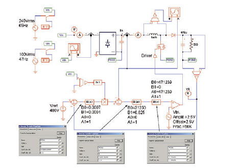
The implementation made with PSIM® in figure 3, is basically composed of the power and control stages shown in figure 2.
The two switches allow us to simulate the circuit for the two most unfavorable conditions of frequency and voltage of the single-phase network, so that initially the power stage is fed with a sinusoidal source of 240Vrms and 65Hz, and after 2 seconds the The power supply will be 100Vrms and 47Hz until the end of the simulation (4 seconds). The rectification stage is composed of a bridge and a filter.
The control stage of the MOSFET is made up of an automatic feedback control system and is designed using two PID networks, one for voltage control and the other for current.
The sine reference input Vin is taken from an isolated meter, Vref is a constant 400V signal, VR is the voltage across the load resistor, and IL is the current across the inductor.
H(s) are the blocks of the PID transfer functions of voltage, current and the filter block respectively.
Implementation of the control system
Regarding the parameters that make up the compensators, the value of the proportional gain of the current loop must comply with equation 4.
Where vosc is the maximum value of the stabilizing ramp. With this it is achieved that the maximum downward slope of intensity in the inductance becomes equal to the slope of the stabilizing ramp, a necessary condition for the stability of the system.
On the other hand, the value of the current loop integral gain is calculated in such a way that it causes a sufficient phase margin. For this, it can be considered that the transfer function of the system to be compensated has the form given in equation 5.
On the other hand, the low-pass filter of the current loop compensator must introduce a pole at a frequency slightly higher than the switching frequency, in order to filter high-frequency signals.
The values of the voltage loop compensator must make the voltage ripple present in the output capacitor very low in the control loop, choosing a small proportional gain value for this, otherwise it would distort the reference signal of current times inductance.
In the value of the integral gain, a zero must be introduced at low frequencies (of the order of Hz), thus achieving an acceptable phase margin.
Specifications for the PFC and simulation parameters
A power factor correction system is simulated with the following specifications: 300 W output power, 47 to 65 Hz network frequency, 50KHz switching frequency and current ripple between 20 and 30%.
This requires a converter with a 1mH inductance and a 470µF capacitor. The simulation conditions will be the most unfavorable. These are:
1º- A network voltage of 100Vrms, frequency of 47Hz, load resistance of 300 W, which cause the maximum voltage ripple at the output and the highest current consumption.
2º- Network voltage of 240Vrms, network frequency at 65Hz, load resistance of 300 W, which cause the minimum current ripple in the coil and a worse power factor.
A transient analysis will be carried out with a final time of 4 seconds, which allows observing the evolution of the output voltage, taking into account the changes produced in the input conditions. The simulation parameters are shown in Figure 4.
Simulation results
The following figures show the simulation results obtained from the PFC system.
Conclusions
The use of PSIM® for the simulation of power circuits provides correct results, and allows us the interaction between electronic circuits, control blocks and sensors in a very simple and intuitive way, so this simulator is very suitable both for beginners in the design and simulation of electronic circuits to carry out projects at an industrial level.
You can view the full content of this article by downloading the magazine in PDF format from the newspaper library.


