Author: Trifon Trifonov
This article reviews a unified methodology for applying security mechanisms (SM) in digital design. The categorization of digital logic has been carried out from the design and perspective of Functional Safety (FuSa). Different SM are proposed for finite state machines (FSM), combinatorial logic and sequential logic according to the recommendations of ISO26262. Sample RTL snippets are shown for all SMs in SystemVerilog (SV), but the proposed schemes can also be implemented in VHDL. A comparative analysis based on the synthesis results has been performed, showing the impact on the chip area with different implementation options. The proposed methodology has been successfully applied to various commercial automotive products.
Introduction
Electronic Control Systems (ECS) embedded in today's vehicles are growing in scale and complexity. Even considering the reliability provided by modern semiconductor technologies, the probability of an error occurring in any of the vehicle's electronic systems is assumed to be high. Depending on the system in which the failure occurs, the life of the driver or passenger could be in danger. To assess, avoid and mitigate this risk, the automotive industry has developed the FuSa electrical/electronic (E/E) standard IEC 61508 and has created a specific automotive FuSa standard: ISO26262 [1][2][3][4] [5]. As a result, the Automotive Safety Integrity Level (ASIL) [1] was introduced and specific requirements were placed on new products, both for the development cycle and for diagnostic capabilities regarding possible random failures. To quantify the latter, different hardware metrics were introduced, since these depend on the ASIL objective of the product.
For ASIL C and D applications, the required Single Point Failure Metrics (SPFM) are 97% and 99% respectively, as almost any error could lead to Security Objective (SG) violation, so it must be detected with high diagnostic coverage. Meeting the stringent requirements of the Probabilistic Metric for Random Hardware Failures (PMHF) could also be challenging for a complex system where transient failures are also considered.
Also, for complex IC designs, system analyzes [1][4] may not be complete and ready before design starts. Without the output of these analyses, IC designers can be hampered from implementing proper fault detection logic where appropriate, right up to the very last stages of the project. In those cases, the proposed methodology should be fully applied in the digital design. When the analyzes are complete and all FuSa-related features are identified, the SMs that are already in place can be reviewed, updated, or even removed if a particular block is covered by another SM.
The easiest and most direct approach to detecting failures in digital logic is to use redundancy. This is not evaluated in the current article because it is trivial to implement, but quite expensive in terms of area (logic doubles or triples and comparison logic is required). Whenever redundancy is used as the SM, the effects of common cause failures must be considered in the dependent failure analysis [4] and managed in the design.
The current article focuses on SMs that can be applied everywhere in all types of digital design. The proposed methodology can be fully or partially applied depending on the FuSa analysis as well as the technical/security requirements of the hardware. The described techniques are applied during RTL encoding, so they are technology independent.
Digital Design Categorization
In general, digital logic can be divided into two main classes: sequential and combinatorial. The main categorization is further expanded in the proposed methodology. The additional category is refined for the FSM logic:
- FSM State/Transition Logic: Combinatorial and sequential logic related only to FSM.
- Common Sequential Logic: All registers or latches that are not related to the FSM logic.
- Common combinatorial logic: all combinatorial logic that is not related to FSM.
The newly introduced categorization is necessary as different SMs are proposed that can be applied independently of each other.
From FuSa's perspective, digital logic can be divided into:
- Main Functional Logic: Failure modes in this logic could lead directly to violation of the SG or, in other words, have the potential to directly violate the security objective (PVSG).
- Failure detection logic: Failure modes in this logic could only indirectly violate the SG (usually in combination with a failure in the main functional logic). This logic implements security mechanisms itself or other logic that cannot directly violate the SG (eg DFT).
Troubleshooting Techniques
Finite State Machine Failure Detection
Depending on the ASIL requirements, it might be necessary to detect faults of up to 3 bits and, in some cases, correct faults of up to 2 bits. The FSM states are coded with a 2-bit or 3-bit Hamming Distance (HD) that allows detection of up to one or two bad bits. The essence of the proposed SMs is to use correctly encoded state values and reuse the default FSM state.
The required HD between states can be achieved with a widely known hot/cold encoding [7]. These codes are quite expensive by area: the number of registrations needed is equal to the number of states. For the same purpose, parity and error correction codes (ECC) are used for the state enumeration values, since they are more efficient and cheaper. The error state in the RTL is the default state that captures the required number of bit misses. If a bad transition is detected, the FSM remains in the error state until it is reset. Critical outputs are put in the “safe/inactive” state. Alternative implementation options, along with self-healing capabilities, are presented in [6].
The following scheme is implemented using the SV function, providing 3-bit distance Hamming codes for FSM states up to 32, where Dx is the respective bit of the binary-encoded state number and Px represents the resulting parity checksum:
- Code word = {D4, 0, D3, D2, D1, 0, D0, 0, 0}
- Resulting code (status) = {D4, P8, D3, D2, D1, P4, D0, P2, P1}
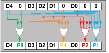
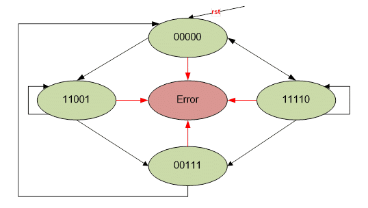
The proposed technique does not require a particular FSM coding style if the values of the enumeration state have the required minimum HD between any two states and the error state is the default where the error flag is set. It could be used with most of the coding styles and implementations proposed here [7]. It is recommended that you log all FSM outputs or ensure that FSM outputs depend only on the current state.
| Up to 4-states | Up to 8-states | ||
| notation | value | notation | value |
| State0 | 01010 | State0 | 000000 |
| State1 | 01101 | State1 | 000111 |
| State2 | 10011 | State2 | 011001 |
| State3 | 10100 | State3 | 011110 |
| NA | NA | State4 | 101010 |
| NA | NA | State5 | 101101 |
| NA | NA | State6 | 110011 |
| NA | NA | State7 | 110100 |
Table 1. 3-bit HD encoded states
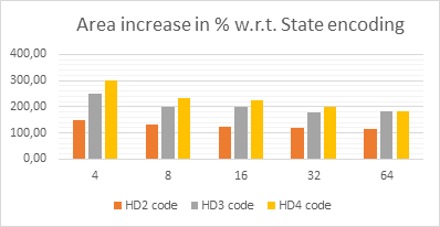
The following diagram shows the area utilization results for different HD codes and the number of FSM states. In some cases, the area overhead reaches 300% of the typical binary state coding for the same number of states.
Common sequential logic fault detection
All functional registers (FSM output registers, memory-mapped registers, counters, etc.) must be able to detect a number of failures as per FuSa requirements, i.e. single-bit failure detection capabilities (by means of the parity checksum) and multi-bit misses. Detection capabilities (via cyclic redundancy check (CRC) or ECC checksum). The suggested mechanism provides continuous control of the next value (combinatory) and current value (sequential) checksum bits. Faults can occur in the next state logic and will not be detected, which is expected since it is used for all downstream logic. Due to the transient nature of bit inversion faults and the fact that there is electrical and logical masking of the signals, the actual effect could be mitigated, making it acceptable for FuSa metrics. A generalized diagram is shown below:

Common combinatorial logic failure detection
Depending on the variety of combinatorial functions, different schemes can be used to detect failures. The following main groups can be distinguished:
- Adders/subtractors and any kind of general arithmetic
- Comparators
- Multiplexers/Encoders/Decoders
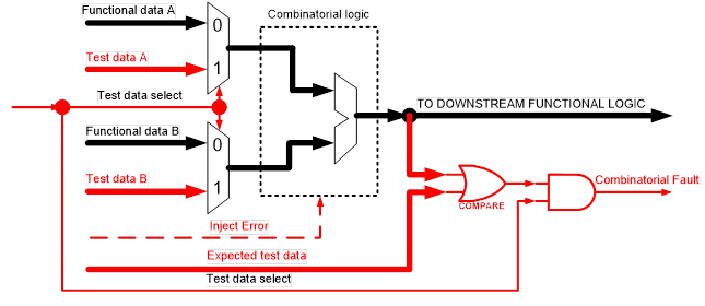
The following approach is proposed. The multiplexers are placed in front of the combinatorial logic to be tested. Designated test vectors are passed and the result is compared to the expected value. Depending on the implemented functions and the selected test vector, the target diagnostic coverage can be achieved. In some cases, it is necessary to apply more than one test vector to achieve the required coverage.
This technique can be applied to combinatorial logic that is not used continuously, that is, it is not used every clock cycle. Since this SM is executed periodically, the Fault Detection Time Interval (FDTI) [5] for the system should be considered.
Detection of latent failures
Another category to consider for FuSa-related products, based on ASIL grade (typically ASIL-C and D), is latent failures. One of the main contributors is failures that occur in the failure detection logic itself. Typically, the method of handling these failures is to test the SMs at power-up, periodically, or continuously. To support that, a simple interface can be implemented that injects an error into the checksum calculation algorithm. The results are checked at the outputs of the logic of interest. In all subsequent RTL samples, latent error failure detection is provisioned and supported.
Implementation in RTL
Derived from the proposed fault detection schemes, the RTL implementation must adhere to a set of coding guidelines. The following convention is adopted for each block that can directly violate SG: three top-level parameters for SV are added along the layout hierarchy. Each of them handles and conditionally instantiates the logic required to detect failures in:
- Sequential logic – SM_FF.
- FSM Logic – SM_FSM.
- Combinatorial logic – SM_COMB.
The above parameters admit the following set of values: 0, 1, 2, and 3. They respectively define “No SM Implemented” and “2, 3, or 4-bit HD”.
Double-bit (2) fault detection is generally sufficient for most application cases. The HD parameter values can be further expanded if necessary.
Generation of ENU sets
For the proper generation of enumeration values of the FSM states, the following pair of function prototypes is introduced:
- F_GET_EST(int seq_num, logical [1:0] SM_FSM);
- F_GET_FW(int total_st, logic [1:0] SM_FSM).
The SV code snippets are shown below:
The proposed approach can be used for FSM state enumeration even for blocks that are not relevant to FuSa with SM_FSM set to zero.
Fault detection record
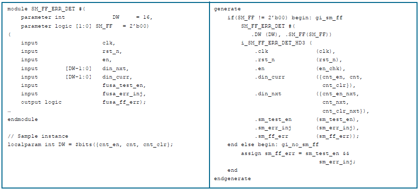
To encapsulate and separate the failure detection logic, a dedicated block is introduced that must be conditionally instantiated in each safety critical block. From the structural point of view, the sequential and combinatorial parts of the logic must be separated, that is, coded in different blocks always in SV. The block port definition is shown below, as well as the sample conditional instance. With this type of module, the designer can add/remove new signals based on project needs and change the diagnostic coverage accordingly.
Combinatorial logic fault detection
There are a couple of approaches that can be implemented during your RTL implementation.
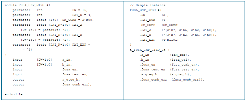
The first approach is to have stand-alone modules for the comparator, adder, and multiplexer that implement all the required test logic, patterns, and vectors. For each of these modules, at the instance level, the designer defines the number of patterns, their values, and the control signal(s) to enable/disable the diagnostic functions. As shown below, all relevant FuSa code related to the comparison must be replaced with a structural description using the instances from the following modules.
The other approach is to have a centralized control unit(s) that have predefined test vectors for different groups of combinatorial logic. This approach is profitable in terms of area, but it is less flexible. Requires tuning of detection logic based on existing patterns.
Results and conclusions
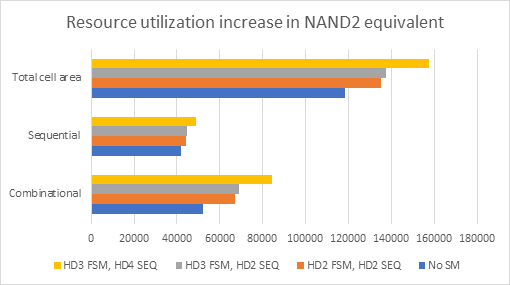
- Area utilization: The methodology allows a sufficiently early estimation of the FuSa-related impact in terms of logic gates. Designers can assess the impact of the area by using different checksums and respective metrics. With these numbers, it is possible to judge whether the CI will be within the projected budget or not, and take corrective action.
- Design Updates – A consistent approach to applying common SMs can simplify design updates during project development. It also speeds up the design phase, allows for easier follow-up, and facilitates design reviews. Enforcing the unified methodology is scalable, structural, and useful, especially on large-scale projects.
- Risk mitigation: Using a library with verified blocks, which implement dedicated SMs throughout the design, reduces overall design risk, such as incorrect implementation of functions or exposure to bugs.
- Flexibility: The proposed approach allows trivial modifications to the part of the design, even in the last stages of design. It can be further enhanced and extended to accommodate different common SMs to address a wide variety of design needs. The methodology can be combined with techniques applied in back-end design flow tools (synthesis, place, and path) for better diagnostic coverage and ASIL metrics.


