Modeling is an efficient and inexpensive way to represent a real world system. A model can represent key aspects of the system, such as the underlying requirements, the components, and how those components communicate with each other. The model can be simulated, allowing designers to test designs before hardware is available, or to test conditions that are difficult or expensive to replicate in the real world. Iterating between modeling and simulation can improve the quality of system design at an early stage and thus reduce the number of errors discovered later in the design process.
Despite these advantages, designers who rely primarily on hand coding don't always take advantage of modeling and simulation. Test setup can be difficult and time consuming, and if separate tools are used for each domain it can be challenging to get a system-level design view. As a consequence, defects that might have been discovered during the modeling and simulation phase are often found during the implementation phase, when it is more expensive to correct them.
These issues have been addressed in Simulink®, a platform for modeling and simulation. Simulink not only supports multidomain modelling, but also simulation, with its own set of Ordinary Differential Equation (ODE) solvers. A basic advantage of using Simulink is that you can represent different domains, such as control systems, state machines, and environment models, in a single model, and then run simulations within Simulink to verify that the model has been built correctly. As the simulation runs, you can access analysis capabilities such as data visualizations, state animations, and conditional breakpoints. Once the simulation has finished, the recorded data can be analyzed with MATLAB scripts and visualization tools.
In this article, we describe a workflow for creating a component model from requirements, simulating and testing that component model, and then connecting it to a system-level model for further simulation and testing. To illustrate this workflow, we will build and test the failure management component of the HL-20, a reentry vehicle designed by NASA to complement the Space Shuttle orbiter. We'll connect our component to a system-level model that includes environment models and flight controls, plus guidance, navigation, and control (GNC); Later, we will simulate the model at the system level to validate its behavior.
The model used in this example is available from the Aerospace Blockset.
Creating the component model from the requirements
The first step is to model the fault management logic of the actuator system. The requirements document states five possible modes for the actuator: passive, standby, active, isolated, and off. For simplicity, we will consider only the first four modes. We represent these modes by adding four states to a Stateflow® state diagram (Figure 1).
Next, we need to determine how the system will transition from one state (or mode) to another. Using the information provided in the requirements document, we add transitions that connect the states and specify what conditions must be met for the system to change states. Also, we group the Passive, Active, and Wait states into a single superstate, since they all go to the Isolated state when the same condition occurs. This hierarchical modeling technique helps us to model complex logic in a visual and simple way (Figure 2).
We continue to build the model, connecting each element to a specific system requirement (Figure 3). Later we can go back in our model to the requirements document to explain why a certain design decision was made.
Once we've created the logic for the left inner actuator, we can reuse that design for the right inner actuator, since the structure is exactly the same. The only items that need to be changed are the conditions related to each transition, as described in the requirements document (Figure 4).
Component check by simulation
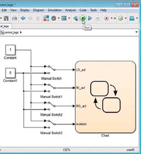
Now that the component is partially built, we're ready to run simulations to check that it behaves correctly. To this end, we set up a simple test framework that brings input signals to the component using a combination of constants and switching blocks (Figure 5).
With Simulink and Stateflow we can start the simulation without having to manually define variables. When you press the Play button, a dialog box appears showing the variables that have to be defined in order for the simulation to run. By clicking OK, these variables are automatically created (Figure 6).
As the simulation runs, the state diagram becomes an animation, letting us know which state is currently active and how the system transitions from one state to another.
An ad hoc test by turning input signals on or off reveals a flaw in the design (Figure 7). When the left inside actuator is activated, the right inside actuator should also be activated. The fact that we were able to configure the input conditions so that this does not occur indicates that our design is flawed.
It turns out that the condition of the transition from Active to Standby has a fault. Since we have linked each condition to a requirement, we can go back from that condition to the underlying requirement and verify that the failure originates in the requirements document and not in the design (Figure 8).
The last line should read “or the left inner actuator is in the Active mode”.
We correct the wording of the requirements document, review the condition, resimulate the model, and check that the system now behaves correctly in response to input signals.
System check with the new component
Now that the FDIR component has been verified independently, we are ready to test it in the system-level model. We embed the component in the model in the form of a Model block with the name FDIR_application. Once the model is integrated into the system model, we can continue to work on it independently of the rest of the system using Simulink's model referencing capability (Figure 9).
We simulate the model at the system level and visualize the behavior of the component in the state diagram, as well as the behavior of the system as a whole, using FlightGear, an open source visualization tool.
To test the system, we set up a framework that injects faults into the actuator system, so that we can check that both the component and the system as a whole respond correctly (Figure 10).
So far, we have created a component from the requirements, simulated and tested that component, and then connected it to a system-level model for further simulation and testing. There are a number of additional steps we can take to improve our modeling and simulation workflow.
For example, we can do the following:
• Implement a formal testing and verification process with design testing, coverage analysis, and test case generation.
• Increase simulation performance using the Performance Advisor in Simulink.
• Replace blocks with hardware connections as hardware becomes available.
• Use tools to check that the design parameters are optimal.
Whichever next step is chosen, the key is to model, simulate and test the system as often and as soon as possible, in order to detect and correct defects early and thus reduce the cost of implementation. development of the system as a whole.


