Compared to traditional connection techniques, flip-chip interconnects offer a better alternative when superior electrical performance and high signal density are required. However, if the I/O planning of the chip is not well planned and optimized for the application, the advantage of eliminating inductive connections that make flip-chip an ideal choice for interconnection can be severely affected.
Applications that require a transmission line impedance of less than 50Ω and low crosstalk between signals require routing of these signals in stripline mode. Stripline routing requires placing the bumps on the chip so that there is optimal exhaust from the chip in stripline mode. Therefore, the arrangement of the I/O terminals on the chip must be a priority depending on the necessary features: the less critical signals can be output as microstrips and the most critical ones as striplines.
Improper layout will cause unwanted leakage of critical signals, ultimately affecting signal performance and/or requiring the package to use more substrate layers than necessary. This can cause a significant increase in the cost of the product.
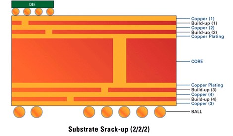
Devices with flip-chip interconnects are typically attached to a packaging substrate manufactured using Sequential Build-Up (SBU) substrate technology. A single core is turned into circuitry using conventional substrate manufacturing processes, and is in turn used as the base to build denser circuit layers. The dielectric layers are deposited symmetrically on the top and bottom faces of the core, maintaining mechanical flatness through a stress balance, either as a liquid or a dry film, and then cured. Vias are then formed by laser drilling through the deposited dielectric layers to connect the circuitry between layers. The circuitry is deposited on top of each layer using a semi-additive process. This process of sequential addition of dielectric and metallic layers facilitates the routing of metallic traces with much finer geometries, with trace widths of up to 12um, which is not feasible with conventional etching processes.
Signal routing optimization for high frequency applications
When optimizing for signal integrity in high-frequency applications, the main goals are interconnect impedance control and crosstalk minimization. If the system is designed to work in a 50Ω environment, each part of the transceiver channel must be matched to this impedance. Any impedance change in the signal path will cause an excessive level of reflections that can destroy data, and depending on the severity of the impedance change, even complete system failure.
Assuming a lossless environment, the interconnect impedance is simply a ratio of the structure's inductance to its capacitance. The inductance is controlled by the region of the loop formed by the signal and its return path. The capacity depends mainly on the width of the trace, the distance to the return path and the dielectric constant of the material that fills the gap between the trace and its return path. The greater the width of the trace, the higher its capacitance and the lower its impedance, and vice versa.
So what does it take to get a 50Ω track on a microstrip routed SBU type flip-chip substrate (the outermost layers)? The answer is: a track width up to 60um wide.
Routing traces with this trace width not only increases the area occupied by the substrate to effective escape pins on a device with a large number of I/Os, but also implies greater routing proximity between the signal traces, which in turn substantially increases crosstalk noise.
Also if the application requires an impedance of 30Ω it is virtually impossible to route such a low impedance using realistic trace widths. In a microstrip environment, the track capacity is only on one face of the track and is entirely dependent on the width of that track.
Embedding the track into the substrate and routing it in stripline format will solve this problem. This is because a stripline environment takes advantage of the presence of return path planes on both sides of the track, effectively doubling the capacitive load and achieving a much lower impedance for the same track widths. .
Decisions for CI planning
The presence of a clean return path is essential to control the impedance of the track and to avoid problems related to signal integrity. A cross section of SBU in 1-2-1 has the top layer followed by a core with 2 sides and then the last layer, to which the solder balls are attached. The core layers are generally not used for signal routing and are typically reserved for device connections to power and ground.
Therefore, in theory there is only one routing layer, which is the 1st microstrip layer, and if the system needs a channel impedance of 30Ω it would be practically impossible to achieve it on a 1-2-1 type substrate.
By adding another routing layer to the construction, such as in a 2-2-2 substrate, the tracks could be integrated in a stripline format on top of layer 2, allowing for low impedance routing.
For devices with a limited terminal area, the pitch and number of I/Os define the size of the chip. As the size of the chip increases, its cost increases proportionally. In an attempt to optimize cost, the I/O pins are placed in concentric rings, thus reducing the size of the chip while achieving the same functionality.
For a given pitch in the terminal area, current restrictions for mass manufacturing may allow routing of up to two rings over a single layer of the SBU substrate. Four rings can be placed with two routing layers of the SBU substrate, and so on.
A device with four concentric I/O rings would require a minimum SBU stacking of 3-2-3. The two outer rings will escape onto layer 1 of the substrate stack in microstrip format. In order to provide a clear reference to routing at Layer 1, Layer 2 is often reserved as the return path. Layer 3 could be another routing layer and the 4th layer belongs to the core of the substrate. The 3-2-3 stacking effectively provides two layers of routing for the I/O pins on the chip such as exhaust and connection to the balls of the package.
Tracks that require low impedance will be more suitable for routing on the inner layers. But if the I/O pins were on the outer periphery of the chip, it would be nearly impossible to route them in microstrip format and still achieve the desired low impedance. Therefore, in practice it is necessary to integrate them in stripline mode.
Using the same I/O layout, but wanting to have the outer rows of I/O in a stripline format, the SBU substrate will need to be a 4-2-4 stack. Layer 1 is for the return path, Layer 2 is for low impedance trace routing, Layer 3 is reserved for another return path; layer 4 is used for other signal routing and then there is the core layer. Thus, for the same I/O arrangement, the number of layers in the SBU substrate increases, which in turn greatly increases the cost of packaging.
However, if the chip schedule had been designed in such a way that I/O requiring low impedance paths were reserved for the inner two concentric rings, and not the outer two, the need for adding extra substrate would disappear, thereby reducing the cost of encapsulation and achieving the desired signal performance.
In summary, it is essential that chip planning consider system performance as well as follow an iterative design process between the IC design and device packaging teams in order to optimize product performance and minimize cost. cost.
It is also necessary to make similar decisions that take into account the planning in the union between the encapsulation and the plate for a perfect integration of each component in the system.


