Alexandru Valeanu of Microchip Technology explains how to use a real-time clock and calendar to implement an electronic clock where the time and date can be set with two buttons
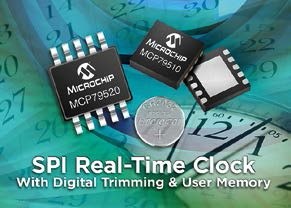
An electronic clock can be built in which the display, time and date can be set using two push buttons together with a real-time clock and calendar (RTCC) and incorporating EEPROM, SRAM, time register with unique identification, a supervisory timer and an event detector module. One such device is Microchip's MCP795WXX SPI RTCC and the project can be done on a PIC18 Explorer demo board using its onboard features such as the LCD accessible via an SPI bus and push buttons. Fig. 1 shows the schematic, including a PIC18 Explorer and the AC164147 SPI RTCC PICtail daughter card. To access the LCD with a minimum number of pins, the SPI of the MSSP1 module is used with a 16-bit I/O expander with SPI interface (MCP23S17). The two built-in pushbuttons are S1 and S2, connected to the GPIO RB0 and RA5. The SPI RTCC is part of the PICtail evaluation board and connects directly to the microcontroller module MSSP1.
Another necessary connection is between the RTCC signal CLKOUT and RA4 (T0CKI), the clock input of TMR0. The RTCC is programmed to provide a 1 Hz square wave on CLKOUT. The TMR0 is programmed as a counter and is initialized to 0xFFFF to provide a software interrupt every second. The SPI connections between the SPI RTCC and the microcontroller are not open drain and therefore no pull-up resistors are used. Secondary connections are open drain inputs or outputs and require pull-up resistors. The CLKOUT signal goes to RA4/T0CKI with no lift and can be programmed to offer frequencies of 1 Hz, 4 kHz, 16 kHz, and 32 kHz. The 8F87J11 microcontroller is mounted on the PIC18 Explorer.
The code for the controllers and the main function can be written in C using MPLAB X v2.10 and the XC8 v1.34 compiler. In this way, an electronic clock can be implemented that displays the six basic variables of time and date on the built-in LCD. These are: year, month, day, hour, minute and second. It includes a setup sequence that sets the same six time and date variables using the two pushbuttons on the evaluation card; S1 is the menu key and S2 is the increment key. At the same time, the code tells the user how to set up and use the time keeping records.
How does it work
The MCP795WXX is an SPI slave device connected to the SPI bus of the microcontroller. The RTCC chip selection is controlled by the GPO pin. The device is selected by driving CS low and then the 8-bit read instruction is transmitted to the MCP795WXX followed by an 8-bit address. After sending the correct address and read instruction, the data stored in the memory of the selected address is shifted on the SO pin. Data stored in the next memory address can be read sequentially by continuously providing the clock pulses. The internal address pointer is automatically incremented to the next higher address after shifting each byte of data. Since the RTCC registers are separate from the SRAM array, reading the RTCC register set will put the address back to the start of the RTCC registers. Also when an address from the SRAM array is loaded, the internal address pointer will return to the beginning of the SRAM array.
The read instruction can be used to read SRAM arrays indefinitely by continuing to supply clock to the device. The read operation ends by setting the CS pin high. The propagation sequence is shown in Fig. 2. For writing, as RTCC and SRAM registers do not need WREN sequence like EEPROM, user can set CS to low state, send write instruction followed by address and then the data to write. Since no write cycle is required for the RTCC and SRAM registers, the entire array can be written in a single instruction. To write data to the array, CS must be pulled high after a full byte has been recorded.
If CS goes high at any other time, the last byte will not be written. Fig. 3 illustrates the write sequence in more detail. The two main functions of the electronic clock consist of displaying the six time and date variables using the microcontroller interrupts and adjusting the variables with the two push buttons on the card. The display operation is performed on the LCD of the card; the format is 24 hours. The display of the variables in real time is obtained whenever the menu key is not pressed. The increment key action has no effect on the clock which continuously displays the time and date. Pressing the menu key launches the setup menu and disables interrupts. The menu covers in this order the year, month, day, hour, minute and second. To go from one variable to another, the menu key is used and the variable is increased using the increment key. The last action of the menu key is to exit the configuration menu. Entering the setup menu does not stop the RTCC oscillator. At the end of the configuration, the time and date variables are updated. If the user enters time setup mode, all variables are written to the RTCC at the end of the sequence, even if they have not been changed. In this case, when the menu is exited the clock will continue counting from the entry point in the setup.
Delays and Controllers
Since the LCD controller needs some delays to process the instructions, some auxiliary delays have been created. Long delays are used to eliminate keyboard debounce or as general purpose delays. LCD controllers handle data, instructions, and strings when entered into the LCD. High level LCD functions initialize or display the date and time on the LCD. The library also includes global variables for time and date.
The RTCC controllers represent the mid-level communications between the PIC1 module MSSP18 and the SPI RTCC. Related functions call on SPI drivers. In addition, the library defines all the necessary constants such as registers, addresses, and masks. The SPI drivers provide the low level SPI communications with the RTCC and their functions are used by the SPI RTCC drivers. The keyboard controller set has only one function. Wait for the selection of one of the two built-in switches: menu key or increment.
After making the selection, the firmware updates the code of the key pressed. Exiting the function gets a value and the function debounces the key twice for 100ms. The function is deactivated only after releasing the pressed key. The interrupts are generated by the overflow of TMR0, which is initialized to 0xFFFF as a counter. The Timer 0 timer is incremented once per second by the CLKOUT signal from the RTCC.
The interrupt function calls the displayed time function, which reads the six related registers from the RTCC and places them in the six global variables (year, month, day, hour, minute, and second). Random byte access mode is used since some versions of the application may use only some of these six variables. In the end, the interrupt function displays these six variables on the card's LCD.
Configuration
The RTCC configuration consists of two stages: RTCC initialization and time keeping register setting. To initialize the SPI RTCC, the SPR RTCC controller header includes two initialization functions. The first function enables the battery via the VBATEN bit in the day register, to set the control register that disables alarms, and to set the MFP pin as a square wave with a frequency of 1 Hz. The second function checks the OSCON bit (day record). If the oscillator is already running, no action is taken. If the oscillator is not running, the time and date are set arbitrarily and the oscillator will start. To adjust the time keeping registers the sequence can be found at the end of the main function and the six time and date registers are updated through the six time and date variables. The use of time keeping registers is to read and display them on the LCD. These two operations are performed by the display timeout function once per second on interrupts. There are two basic functions to access the RTCC registers: one for writes and one for reads. Both use register addresses within the SRAM zone of the SPI RTCC. Based on these addresses, only the register addresses will be differentiated in the basic read and write functions. The readings are used in the interrupt function. The writes are used in the initialization function and in the configuration script.
Conclusion
This article has explained how to control, display and configure an electronic clock based on Microchip's MCP795WXX SPI RTCC. The project has been made using the resources of the PIC18 Explorer demo board. The code was written in C and the microcontroller used was the PIC18F87J11.
Tags
time control


