Author: Boris Adlung, Rigol Technologies Europe
"What do I need a probe for? Will I be able to use the probe to take all the measurements? What advantages does this instrument offer?” These are some questions many developers ask when getting a new oscilloscope up and running.
a logical connection
The probes help connect the oscilloscope to the object under development when making the measurement. There are different probes to carry out various types of tests. For example, currents can be measured with a clamp meter, while digital signals can be recorded and displayed on a digital storage oscilloscope (MSO) with a logic probe and the necessary interface. The aim of instruments in general is not only to create a simplified contact between the measuring device and the object to be measured, but also for the measurements to offer a very high accuracy of the signal.
It is important that the influence added by any type of probe is as low as possible so that it does not affect the signal source, ie the test object. In a measurement setup it is also important to know what you want to measure; for example, detection of unwanted radiation should be minimized or completely eliminated.
Unlike a test lead, probes establish a high-quality connection with a simple connection. A high measurement resistor prevents the capture of unwanted interference or noise from the network. The high measurement resistance makes it possible to pick up an ideal voltage on the probe and thus establish an optimal connection to the oscilloscope.
joint input resistance
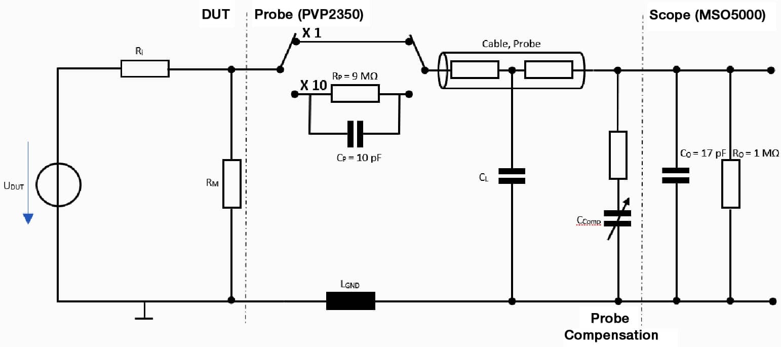
A passive probe, for example, has two contact points: the active terminal and the ground connection. For the active connection, the passive probes have a hook that can be easily attached to the circuit and a connection to earth by means of a short length cable with an alligator clip. In addition to the practical connection head, the probe consists of a coaxial cable with a BNC connector. Together with the oscilloscope, the probe defines the input resistance of the measurement. The oscilloscope has an input impedance of 1 MÙ and low capacitance for bandwidths up to 350 MHz or 500 MHz. In the case of a direct connection, this capacitance places a load on the device under test, which means that the probe should add a reduced capacity so that this load is still small.
Voltage range and bandwidth
A passive probe also has two settings that can be used to obtain a voltage divider. For the normal x1 setting, the signal is applied to the oscilloscope at 1 MÙ, using the probe without the voltage divider. The measured values are then passed to the oscilloscope 1:1. In this case, not only the maximum voltage range is limited, but also the bandwidth. Higher voltage and bandwidth values can be achieved with a 10:1 configuration. However, in such a case the oscilloscope must also be set to 10:1 for vertical adjustment to display the correct amplitude. In the 1:1 configuration together with the oscilloscope, the following measured resistance Z is obtainedM:
![]()
Formula 1: Resistance measurement of the probe (x1) together with the oscilloscope.
Here you can see that the ground wire (GND) is inductive. The longer this wire is, the more inductance it has. From the formula it can be seen that if ù increases (ie the bandwidth), this resistance also increases and so does the influence (see Figure 2). It can also be seen from formula 1 that the capacity creates a resonator. As a result, higher bandwidth measurements will show an excessive value which can be reduced by shortening the GND wire.
For each millimeter of GND cable, an induction of approximately 1 nH is generated. The shorter the connection to ground at high frequencies, the better. Shorter connections can be made with a ground spring to minimize these effects. The x1 gain factor can be used in measurements that require recording a low bandwidth and low voltage. Therefore, most measurements within the normal voltage/bandwidth range will preferably require the x10 gain factor. For the example of the PVP2350, the standard probe of the MSO5000 series of oscilloscopes, both amplification factors can be set. In this case, voltages up to 30 V can be measured.RMS to x1 and voltages up to 300 VRMS in the x10 range. Therefore, the stress is increased by a factor of 10.
oscilloscope.
The lower capacity of the probe also increases the bandwidth from 35 MHz to 350 MHz. Figure 1 also shows a connection for x10. Neglecting the resistance of the coaxial cable (since it is << RO y RP), the voltage divider according to formula 2 is now created when the time constant as expressed in formula 3 is taken into account.
![]()
Formula 2: With a voltage divider set to x10, the capacitances decrease using the same time constant as Formula 3.
![]()
Formula 3: Time constant for the voltage divider at x10.
In most applications, measurements can be taken with this bandwidth and voltage values at x10. In this case you also have to set x10 on the oscilloscope for vertical adjustment. When using a probe with an oscilloscope, you must always take into account the bandwidth of both elements (probe and oscilloscope). The 3dB bandwidth is significantly influenced by the probe so it should be taken into account when purchasing the oscilloscope. If the system bandwidth is too low for the application, a probe with a higher bandwidth should be used.
In figure 1 a compensation has been integrated. In this case an adjustable capacitance has been fitted to the probe, and for the PVP2350 it can be reset between 10 pF and 25 pF with the supplied screwdriver.
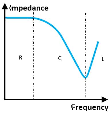
Higher impedance measurements are no longer used in higher bandwidth applications. The goal here is to achieve circuit tuning (usually 50 Ω) in order to avoid unwanted reflections. If a probe is needed for high frequency applications, active probes can also be used instead of passive ones. To make the right decision it is essential that the amplification factor can be applied in a certain bandwidth and at the same time does not influence the circuit too much.
Amplifiers and clamp meters
Active probes integrate a broadband linear amplifier that must be powered. In addition to bandwidth, the active device achieves very high signal accuracy with low input capacity. Its drawback is the limitation of the input voltage (eg, the maximum voltage that can be measured with the PVA8000 is 30 Vpeak).
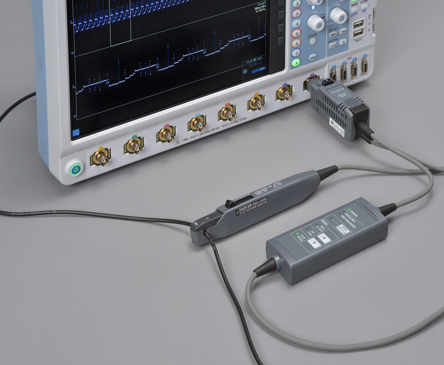
Clamp meters offer a connection option for measuring currents. Since an oscilloscope is a voltage meter, these currents have to be converted into a voltage value. As the voltage/current conversion is known from the clamp meter data sheet, the current can be displayed and measured on the oscilloscope using the amplification and unit [A].
Clamp meters are based on a transformer where the measurement line represents the primary winding and the clamp meter represents the secondary winding. This is how alternating currents can be measured. Direct currents are measured with a Hall probe.

differential probes
Differential measurements are needed when measurements are taken between two values of potential voltage. There are two options available to carry them out. On the one hand, a high frequency differential probe is required for fast differential data signals such as Ethernet or LVDS. On the other hand, differential probes are needed in the field of high voltage measurements if you want to measure voltage differences that do not take earth as a reference. For lower frequencies, these measurements can also be displayed using two passive probes (channel 1: potential 1, channel 2: potential 2) and a math function (channel 2 – channel 1). However, these measurements contain noise, errors can occur during their operation between the probes and the maximum input voltage of the passive probes must be respected.
A key issue to consider in differential probes is the common mode rejection factor (CMRR). Common mode changes are unwanted simultaneous changes in potentials 1 and 2 with respect to ground that are visible at the output since only the change between potentials 1 and 2 is measured. This refers to the amplification factor of the differential mode compared to common mode, which should be much higher. This value depends on the bandwidth. The PHA2150 high voltage differential probe has a bandwidth of up to 200 MHz and the maximum differential voltage that can be measured is 1500 V. CMRRCC is >80 dB and CMRR1MHz is >50dB.


