Thermal management of boxes for electronics
Electromechanical and electronic miniaturization leads to ever higher connection density, which in turn makes electronics ever hotter.
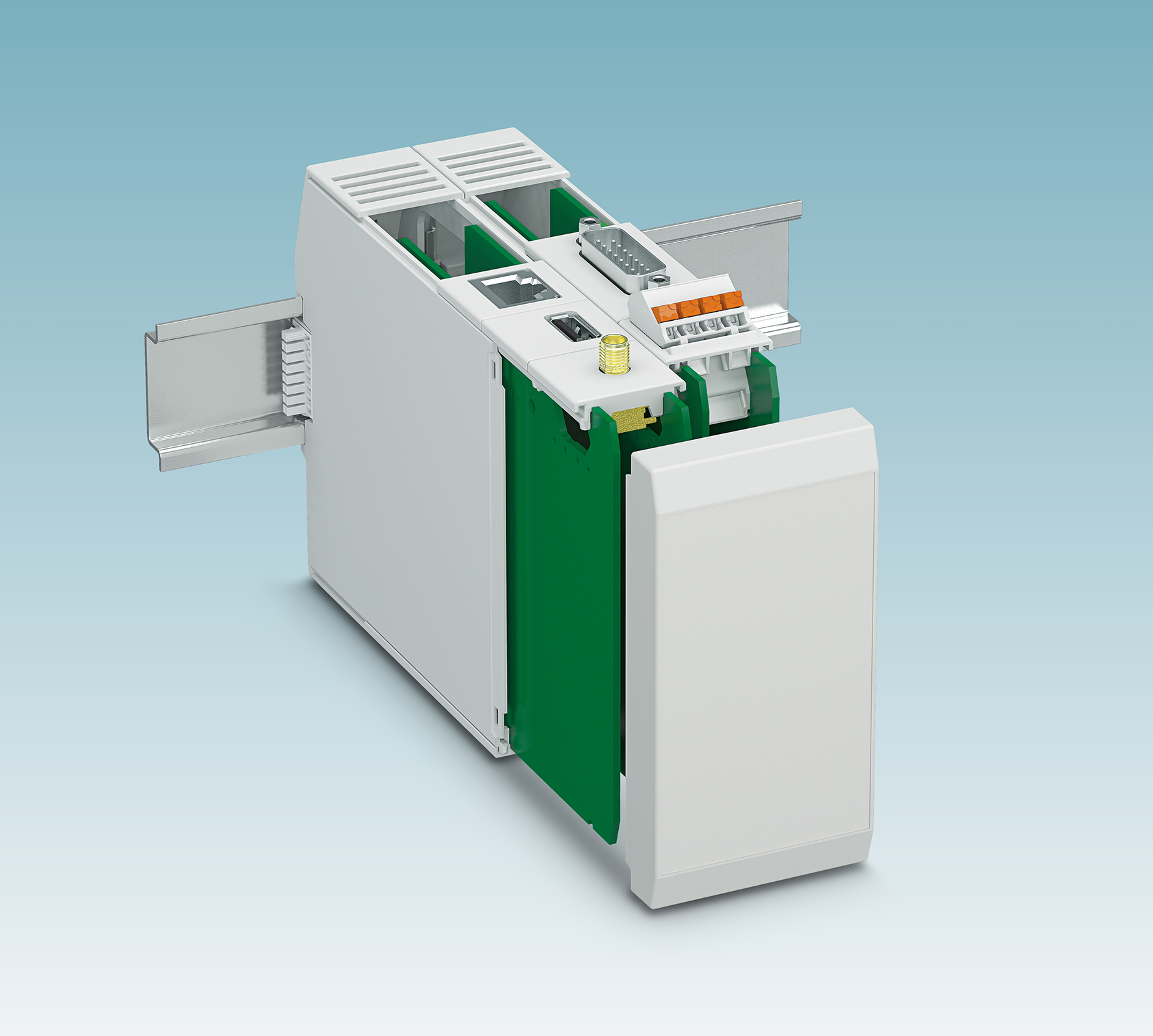
Passive heat sinks from the ICS electronics enclosure family from Phoenix Contact mean that the devices can now be used even in thermally demanding applications. Using extensive thermal simulations, Phoenix Contact also supports equipment designers in optimizing their PCB layouts (main image).
Electronics enclosures must house much more than the printed circuit board with electronic circuits. The electrical connection for power supply and signal transmission must be taken from the outside to the printed circuit board, and from the PCB to the outside again. Enclosures must be as compact as possible and offer protection against contaminants and dirt, as well as against accidental contact with live parts inside. And in addition to all this, an additional problem must be taken into account: heat. If high-capacity processors or even power semiconductors are used on a printed circuit board, with unavoidable power dissipation, it can become extremely hot.
Ventilation slots, fans and cooling fins
One option for dissipating heat uses the physical direction of flow. The case would be equipped with ventilation slots so that once it is placed on a DIN rail, air that has been recirculated and cooled can flow through it. The heat loss generated by the component will dissipate upwards. Components subjected to thermal stress should be mounted near the bottom ventilation slots to allow "fresh air" to circulate around them.
At the same time, other thermally sensitive components should not be subjected to the impact of these hot spots.
The width of the ventilation slots plays a key role; below 2 mm, they are practically ineffective,
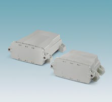
and above 2,5 mm limit the desired protection against contacts. Side panels with the required number of ventilation slots can be attached to Phoenix Contact ICS boxes (image 2).
When it comes to improving the circulation of cooled air and preventing heat dissipation from causing heat buildup, choosing a larger enclosure can also be beneficial.
Likewise, the effects of physical perfusion can be mitigated by active elements such as fans, which cause the airflow rate in the case to increase rapidly, allowing much more heat to be dissipated. The main disadvantages of a fan are its power consumption and its risk of failure. Cold refrigerated air allows a significant proportion of contamination to enter the case, and equipment designers often do not want moving components in their applications.
Peltier elements, thermoelectric coolers, are also a possible solution, but due to their power consumption and the cooling capacity they can achieve, they have only limited utility.
If the normal convection of air flowing through the case is insufficient for cooling, passive heat sinks, made of heat-conducting metals such as copper or lighter aluminum, are the best alternative. To significantly increase the surface area of the heatsink, fins can be added to aluminum heatsinks using an extrusion process.
Boxes for electronics ICS (Industrial Case System)
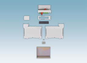
All these factors have been taken into account during the development of the thermal management concept of the ICS enclosures, now available in widths of 20, 25 and 50mm. This enveloping solution features innovative guide and push-in technology. Using the system's guide technology, PCBs equipped with the necessary connection technology are quickly and easily inserted into the bottom of the housing, snapping into place. Connection technologies housed between the rails include connector base housings, RJ45 and USB connections for Industry 4.0 applications, and SUB-D and antenna connections.
The mounting system facilitates the integration of heat sinks that, in this way, can be placed directly on the printed circuit board, connecting to the component by thermal conduction. The printed circuit board with the attached heat sink can then be inserted into the casing and become part of its outer structure. With this solution, considerably more heat is dissipated than in an application without a heatsink.
With a 85°C heat source on a PCB and a thermal coupling with an aluminum heatsink, a maximum power of 28 W would be dissipated at an ambient temperature of 20°C. At 40°C, 15 W would be dissipated, and at 60°C, 6 W would still be dissipated. For good heat emission, the hot spot should be located as close as possible to the center of the heatsink and optimally thermally connected (image 3). .
Simulation, design and tests
But how can you simulate the thermal behavior of a case with software and analyze the design of the intended hardware configuration? Simulation enables electronics developers to avoid placing components in heat-critical positions and to include proper heat dissipation measures in their PCB and equipment designs. For simulation and dimensioning support of thermal management, Phoenix Contact offers designers a tiered service.
The information in the data sheets for electronics and electronics boxes indicates whether the enclosure can provide the expected power dissipation without additional measures. If the estimates and design are not correct based on this information, developers can generate their enclosures and assign the necessary connection technology in the online enclosure configurator, as well as download the bill of materials, 3D data, and the schematic of the printed circuit board. In the simulation tool, designers define the position, orientation, and ambient temperature of the equipment in the control cabinet. They then position hot spots on the printed circuit board and specify the maximum expected heating at these spots.
Up to three hot spots can be entered in a free simulation. All information entered, including contact details later, will be automatically stored in an XML file and transferred to the simulation tool via the Internet. The data is imported into the tool, processed, and sent to the client in a predetermined format.
Customer-specific simulation as another service
If the customer requires customized support in the simulation, such as when more than three hot spots have to be examined or when the initial combination does not allow sufficient heat dissipation (image 4), Phoenix Contact is your development partner for the thermal design.
Various simulation studies would optimize the positioning of hot spots and Phoenix Contact would recommend improved heat dissipation strategies, including the use of heat sinks.
Looking to the present and the future
The increase in connection and power densities in electronics means that efficient heat dissipation is required in electronics enclosures. Until now, housing and component suppliers have been unable to provide a solution for electronics developers facing this challenge. With the new thermal simulation tool from Phoenix Contact,
equipment designers can place hot spots on printed circuit boards and define properties. The simulation generates the thermal profile of your electronic designs. Using the simulation results, they can analyze the risks of failure and counteract them with heat dissipation measures.
In addition, Phoenix Contact's ICE heat dissipation technology is now available. Designed to be used with ICS electronic boxes, with this technology users can develop new fields of application for their ICS plastic enclosures, such as the use of embedded systems and power electronics to control motors with high heat generation. For other electronics enclosures, including the ME-IO, UCS and ECS series, users will also be able to access web-based support in the future, thus enjoying personalized support tailored specifically to their application (image 5). .


