“Although the first prototype was made using an NI cRIO-9076 device together with the NI 9221, NI 9264 and NI 9225 modules, the final version of the ECU emulator/simulator has been made using an NI sbRIO-9636 device which has allowed us to reduce costs when facing the serial production of the ECU emulator.”
The challenge
When the ECU that controls the injection and/or ignition systems of a vehicle's combustion engine stops working. Read correctly, there is great ignorance on the part of mechanics and electronics on how to address this problem.
We want to provide them with a tool that allows them to diagnose such ECUs in a simulated off-vehicle environment.
The solution
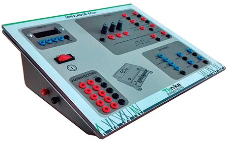
Using an NI sbRIO-9636 device programmed in LabVIEW together with a self-designed signal adapter card, a vehicle emulator has been built. This emulator is capable of sending the most important signals that an injection and/or ignition ECU needs to function outside the vehicle and verify its correct operation in different situations.
Context
In recent years, electronics have been progressively introduced into vehicles. Today it is impossible to imagine a vehicle that does not have numerous electronic control units (ECUs) dedicated to the control of all kinds of vehicle systems such as the control of the injection and/or ignition systems of the combustion engine, the ABS brakes, etc.
One of the most important ECUs is the injection and/or ignition ECU of the engine since when it fails the vehicle is immobilized in most cases.
The development in vehicle electronics has not been accompanied by adequate training on knowledge in electronics for professionals in car repair shops and dealers, which generates a certain fear of dealing with these systems. Therefore, the mission of this project was to provide means to bring vehicle repair professionals closer to the world of automotive electronics.
Technical requirements
The emulator must allow feeding the ECU in the same way as when it is integrated into the vehicle. These power supplies must be suitably protected against possible short circuits that may inadvertently occur when making the necessary connections.
Next, the emulator must send to the ECU the simulated signals that the different sensors that a combustion engine incorporates send to it when it is operating inside a vehicle. We are talking about signals such as the revolutions per minute at which the engine is turning, camshaft position signal, engine temperature, amount of air intake, intake manifold pressure, etc. Some of these signals are considered primary signals and must be sent if the ECU is to be put into operation, while others are secondary signals and help to vary the engine's operating conditions. Another necessary condition is that the repair technician can easily vary these signals in order to simulate different engine operating situations and check the ECU's response to them.
It is also important that the emulator allows quick connection to it of certain actuator elements that a combustion engine normally incorporates, such as injectors, ignition coils, etc. with the purpose of verifying the correct operation of the ECU through the observation in an oscilloscope that incorporates the emulator itself of the form of the electrical signals that the ECU sends to them, signals that in turn are saved on the disk for its subsequent processing and analysis.
Finally, the emulator must allow a vehicle diagnostic machine to be connected quickly and easily to communicate with the ECU and see if it responds to the stimuli that are sent to it from the emulator.
Hardware
Although the first prototype was made using an NI cRIO-9076 device along with the NI 9221, NI 9264, and NI 9225 modules, the final version of the ECU emulator/simulator has been made using an NI sbRIO-9636 device that has been coupled a signal adapter card of its own design, which, in addition to isolating the signals coming from the vehicle, adapts their voltage levels so that they can be correctly interpreted by the NI cRIO-9076. This has also allowed us to reduce costs when facing the serial production of the ECU emulator.
Software
LabVIEW has been used both for programming the emulator and for programming the distributable executable that can be used by workshop personnel.
The possibility of programming at the FPGA level has allowed acquisition at very high frequencies without data loss. In addition, using the tools available to LabVIEW for managing large volumes of data in real time (mainly RT FIFOs and network streams), it has been possible to create an interface in which the end user can observe in detail the operation of sensors and actuators that They operate at high frequency.
Description of the operation of the ECU emulator
First you have to properly connect the ECU to the emulator. Next, from the computer that works together with the ECU emulator, we select the type of ECU that we are going to diagnose through the corresponding menu. This step is important since each ECU needs a particular type of signals to start working. The emulator is prepared to work with the most commonly used ECUs currently and new models can even be incorporated in a relatively simple way.
Finally we start the simulation process. The emulator will send the corresponding signals to the ECU and it will start up, which we will be able to observe physically and aurally. Likewise, we will be able to observe in the oscilloscope that appears on the computer screen if the shape of these signals is correct.
The operator will vary the parameters of the simulation signals such as engine speed, engine temperature, etc. at his will and will check if the output signals from the ECU accompany these changes in the signals sent. You can also connect a diagnostic machine to the ECU through the emulator's own console and through its parameters menu, observe that the ECU understands and reacts to the changes that the operator makes on the signals that are sent to it. .
The entire test is recorded in the form of a file that can be consulted once the test is finished.


