Have you ever wondered why your laptop, phone or even your calculator has a CE Mark label declaring its conformity to the Electromagnetic Compatibility Directive? Why does the EU require compliance with these Directives? The reason is simple to understand. It all comes down to electronic devices where there are digital circuits that switch at high speed. In a digital circuit, its fastest commutations have frequencies much higher than 10 kHz and therefore it becomes a transmitter of electromagnetic interference (EMI) that can affect other neighboring equipment and telecommunications. The Electromagnetic Compatibility Directive (EMC) has as its main objective to protect the radio spectrum, to prevent telecommunications from being affected by EMI from electronic equipment. The current EMC Directive is 2004/108/UE and in April 2016 it will be replaced by 2014/30/UE.
A good example of how to check that any small electronic product generates EMI is to use the TV remote control together with an OM (Medium Wave) pocket radio. We tune the radio to a frequency with no stations in the OM band, where only noise can be heard. With the remote control of the TV we press one of the buttons. The digital pulse train that is heard on the radio, in the form of increased noise, is due to the switched current due to the consumption of the remote's infrared emitting LED. As the other buttons are pressed, different pulsing noises are made. Thus, a cheap OM pocket radio proves to be a useful tool for finding EMI sources. Let's see below how to operate to solve EMI problems in equipment and facilities.
Methodology
Faced with an EMI problem in an installation or in a piece of equipment, we must follow a methodology in order to solve the problem. The investigation process for solving EMI problems is almost identical to the approach used for other types of problems.
We can divide this approach into six basic steps. It is important to follow the steps as indicated, without changing the sequence or skipping any points:
- Gather the basic information.
- Develop an action plan.
- Select the right tools.
- Investigate the problem.
- Select the solutions.
- Verify the performance of the solutions.
Let's see it in more detail below:
This is the most important step in investigating EMI problems. At first, little is known about the operation and characteristics of the affected equipment. If you have more meaningful information, the investigation will be easier. A coordinated meeting between all affected parties is usually a good first step. Of course, the best information is obtained by asking the right questions and taking detailed notes during the meeting with the affected teams. It is common for the different affected parties to disagree with each other, especially if preliminary opinions have already been formed. A common knowledge base on the problem should be established, keeping an open mind and encouraging all parties to do the same. What may appear to be unrelated information can become an important clue to the correct identification of the EMI problem.
Figure 1 contains a list of important questions that will help to follow the correct approach in finding the solution. Some questions can be directed to a specific person and then to several other people. The operator of the troubled equipment or facility spends more time with the equipment malfunction than anyone else, so this operator will have more details of the problem.
Use the information collected in the meeting to determine if the investigation will focus on radiated emissions (the space inside and outside the facility) or conducted emissions (within the facility). If you don't get enough information to determine this, don't worry. Most EMI problems are associated with radiated environments, so most likely you will need to start investigating for radiated emissions. If possible, schematics of the installation or equipment should be obtained. Figure 2 lists the elements that must be included in the action plan.
To detect radiated emissions, researchers usually start by using an OM pocket radio. RF field strength meters, spectrum analyzers and specialized antennas can then be used. For conducted emissions, an impedance matching network (LISN) may have to be used if available or voltage probes in conjunction with a spectrum analyzer and, in some cases, network line monitors and oscilloscopes. In facilities it is better to use portable equipment.
Most antennas are specifically designed to measure radiated electric or magnetic fields well. It is most usual to measure radiated emissions from electric fields because many EMI problems are the result of radiated emissions that occur in the far field. In the far field, with respect to distance, the electric field is 377 times stronger than the magnetic field. When emissions occur in the near field (where the field strength is, with respect to distance, comparable), it may be necessary to measure magnetic fields with loop antennas. High-frequency current probes (must be at least 250 MHz, though they can be as high as 2 GHz) measure conducted emissions on power or signal cables.
Locating the EMI sources of an EMC problem can seem difficult, even for experienced investigators. But good work through the steps of the information-gathering process often reveals the clues needed to find the sources. As the investigation progresses, additional clues will become apparent and, at best, several possible causes will become apparent. In most cases, you should start with the affected computer. There are some simple measurements that can be taken to determine if radiated or conducted emissions (or a combination) are causing the problem. For example, an uninterruptible power supply (UPS) with a charged battery can be inserted between the source of the power supply and the equipment. Do not move affected equipment from the location where it is malfunctioning. If the equipment continues to malfunction, then it is reacting to radiated emissions. If it does not work badly, the cause is the emissions conducted through the electrical network generated by some nearby equipment in the installation.
Another key factor is to see how the affected equipment operates. There are many types of electronic equipment that contain monitors, displays, and meters that can indicate when and how the EMI source affects them. For example, if you look at these devices and can correlate the observations with the noise detected by an OM radio, you can become familiar with the sounds of the radiated emissions received by the radio.
The same can be done with emissions captured with a spectrum analyzer. However, it may be necessary to spend several hours familiarizing yourself with the equipment before discovering a correlation. If the cases are sporadic, it could be that the source was an infrequently used part nearby. If the problems are periodic, a commonly used piece of equipment may be the culprit.
Intentional radiators, such as broadcast transmitters, generate emissions for a specific purpose. Unintentional radiators generate emissions as a byproduct of their normal or abnormal operations. Once the research data is collected, patterns of behavior must be sought. Component frequencies measured with a spectrum analyzer will provide useful clues. Knowledge of the operating frequencies of nearby broadcast stations and the operating frequencies of the various devices in the facility will help determine which devices may be suspected of giving EMI problems. This will lead you to possible solutions to resolve them.
In choosing a solution for each problem, we must carefully consider the operations of the facility, the electromagnetic environment, where the equipment must operate, and the performance of the affected equipment. The safety, cost, installation, maintenance, aesthetics, and performance of the possible solution must also be evaluated. What can be done to minimize the impact of EMI on equipment? It is a matter of levels. What level of EMI determines how much or how little we have to minimize them? When the EMI problem appears in a piece of equipment or installation at the place of use, the levels proposed by the standards are not taken as a reference, contrary to what happens when it is in the design phase. The most common solutions to EMI problems include improvements to shields, filters, and some grounding techniques.
Filtering is commonly used to solve driving emissions problems. Common mode chokes can be used effectively on data lines and power cables.
Shields can be used to solve radiated emission problems. Correction of grounding problems can reduce both radiated and conducted emissions depending on the circumstances of the EMI problem.
By systematically braiding all unshielded cables, low frequency EMI (up to about 100 kHz) is reduced thanks to the conductor pairs (signal and return), which, being together, reduce EMI in common mode, by affecting both at the same time. drivers. But before applying these solutions, an initial effort should be made to reduce emission levels, from EMI sources. It is always more efficient.
If necessary, official verification in a laboratory should take place after the solutions have been applied to the facilities and equipment and returned to normal. Include “after” measurements in a final report. With the final report already completed, the problem can be considered solved.
EMI problems
In EMI problems there are basically two aspects to consider: emission and susceptibility and in both cases: conducted and radiated. A closer look at these aspects will give clues as to how to proceed. Problems discovered during EMC testing are definitive, with specific frequencies and specific levels. Problems discovered at the point of use of the equipment are much more difficult to determine, since the cause of the problem may not be obvious. In this case, it will be necessary to identify the cause before taking effective corrective measures. Let's see a summary of these four basic aspects, how they occur and when they occur.
Figure 3 presents a general map of the CEM problem. During the design and development process of new electronic equipment, every technician involved in the EMC compliance process will be involved in troubleshooting EMI issues, wherever they may arise. Frequently, problems are discovered during CEM testing, rather late in the product development cycle. Arriving late always implies higher development costs, higher unit costs in production, and delays in planning. The best and most appropriate thing is to carry out preliminary pre-evaluation tests of the equipment during the design stage. By performing these pre-assessment tests, EMI problems can be discovered early enough so that corrective actions can be applied in a timely manner, ideally at the PCB level, with lower development costs. It often happens that the electromagnetic environment where the equipment must finally operate is more severe than that proposed by the EMC standards selected to test the equipment. This can be a problem, as EMI problems appear when the customer is already using the new equipment. These problems may be due to weak electromagnetic performance of the equipment or incorrect installation. This situation must be avoided so as not to incur high costs when applying the solution and so as not to lose the image of a good company before our client. For this reason, it is important to apply the EMC standards according to the more or less severe electromagnetic environment where the equipment or installation must work.
In each of these situations, a wide variety of problems can occur. There can be multiple problems at the same time and there is usually more than one solution for each problem. Considering the wide range of problems, it may seem that solutions to EMI problems can be found haphazardly and hit or miss is just a matter of luck. Nothing is further from reality. A reasonable method can be formulated to minimize EMI problems. You can never guarantee that a solution will be foolproof, but with a good method, many problems can be solved.
Transients and continuous waves can cause problems. Transients tend to create digital errors while continuous waves tend to cause errors on analog signal inputs. The emissions tend to come from low-impedance circuits, such as output drivers and switching power circuits, and affect high-impedance circuits, which tend to be susceptible, such as operational amplifiers and feedback circuits in power regulators. strain.
All EMI problems have three common elements: At a minimum, there is always an EMI source, an EMI sink, and a coupling path from the source to the sink. Usually, it is not possible to eliminate the source or the sink, so it only remains to attack the coupling path. Figure 4 shows some possibilities. Depending on the problem, the source or receiver (or both) may be obvious, but is sometimes more difficult to identify. As sources of EMI we can have: microcontrollers, video controllers, digital circuits in general, switching power supplies, inductive loads, motors, electrostatic discharges, radio transmitters, RF heaters, electrical disturbances in the network and lightning. As coupling paths we can find: radiated fields, capacitive crosstalk, inductive crosstalk and coupling driven by signal lines, by power supply or by ground. As EMI receivers we can have: microcontrollers, digital circuits and analog circuits.
We can use a set of variables in the identification of key parameters for problem solving: Frequency – Amplitude – Time – Impedance – Dimensions. Once the source and receiver have been (perhaps tentatively) identified, the next steps are to identify these variables:
Frequency: Identifying problem frequencies is the first step in troubleshooting. All corrective measures depend on this information. The results of the EMC tests will provide this information. But at the place of use it may take some guessing. It is convenient to estimate the bandwidth of the suspicious signals.
Amplitude: What is the amplitude relative to expectations? Is it a minor issue, in which case a few minor fixes might be enough? Or will greater efforts be required?
Time: it can have several aspects. Is the problem continuous or sporadic? During EMC testing, EMI problems may appear during a particular operating state of the equipment. If they appear at the place of use, it may be at a certain time of day or year.
Impedance: it is a factor to consider in the inputs and outputs and in the design of the filters.
Size: depending on the frequencies of the problems, the suspect antennas can be found in the maximum length of each opening, in the length of the cables or in the box.
EMI problems that arise at the point of use are almost always more difficult to correct than problems in the EMC test lab. In a test lab, failures are specifically identified with calibrated instruments and the effectiveness of solutions can be easily assessed. At the point of use, the source of the problem is often unknown and may also be intermittent. The failure can sometimes occur seemingly randomly and there may not be an obvious source of EMI. So the main problem is to find out what caused the failure and then correct the problem, to be sure that the problem has been fixed.
emission and susceptibility
Excessive emission from electrical and electronic equipment is detected almost exclusively during EMC testing and is the test that most often fails. In standards, limits are set to prevent EMI from affecting potentially sensitive and nearby receptors. In household equipment, emissions are usually too low to pose a threat in the vicinity of ordinary electronic equipment if it bears the CE Mark. Consequently, emissions problems are rarely found at the point of use.
On the other hand, in industrial equipment, the switching of large inductive loads can affect other equipment in the place of use. But these problems are sometimes not discovered during EMC testing because actual loads are often difficult to reproduce in the laboratory. This is another reason for the uncertainty in the place of use.
Susceptibility to EMI emissions going into the equipment, as opposed to EMI coming out of the equipment, is the opposite of EMI emissions, and as such, the solutions are largely reciprocal.
Radiated and Conducted EMI
EMI can enter or leave equipment by conduction (through a data or power cable) or by radiation (through the equipment or through a data or power cable). To understand why equipment radiates, we first have to understand what facilitates the radiation. Effective radiation requires a suitable antenna to receive or transmit, which necessitates a metallic element with a length that is a significant fraction of the EMI wavelength. So, the first thing is to establish the wavelength of the EMI signal (continuous suspect wave):
l=300/f
where:
f: frequency in MHz
l: wavelength in meters.
For digital or transient signals, the pulse bandwidth should be used, which is estimated according to the formula:
AB = 0,5/tr
where:
AB: bandwidth,
tr (rise time) = rise time of the digital or transient signal,
As an example, an electrostatic discharge (ESD) has a rise time of 1 ns, providing a bandwidth of approximately 300 MHz (l = 1 meter).
Once the EMI wavelength is determined, we need to look for metallic elements with a wavelength greater than about 20/4. Actually, resonances appear at l/2 or l/4, where the radiation is almost optimal. So anything metallic that comes close to /XNUMX can be significant.
This applies to dipole antennas (such as wires), slots (openings in metal boxes) that act as antennas, and loops (internal wires and traces on the printed circuit board). Figure 5 gives some representative dimensions as a function of frequency.
The bottom line is that low frequencies do not radiate effectively, as there are few metallic elements large enough to behave as a good antenna. At 30 MHz, where radiated emission tests begin, the only good metallic elements to serve as effective antennas are cables. The dimensions of the box, being much smaller, do not become an antenna to consider until around 300 MHz (l = 1 meter, l/4 = 25 cm).
Instead, high frequencies don't conduct well, due to the inductance of the wires, so conducted emissions are very much a low frequency problem. In general, radiated EMI frequencies tend to be in the low hundreds of MHz, making cables prime suspects. When the radiated emission limits are exceeded in laboratory tests in the frequency range below 200-300 MHz, the EMI problems are due to the cables.
When the overshoot frequency range is above 200-300 MHz, then EMI problems are due to ICTs.
Low frequencies, such as those generated by switching power supplies and motors, tend to dominate below 30 MHz. There can certainly be radiated emission problems below 30 MHz and conducted emission problems above 30 MHz. Automotive and military standards require tests with considerable frequency overlap, but this is not the case for commercial standards, where conducted emissions tests typically range from 9 kHz (or 150 kHz) to 30 MHz. Radiated emission tests start at 30 MHz and end at 1 GHz, in some cases reaching 6 GHz.
Identifying the source of EMI
To identify the source of EMI in an installation it is good to use some common sense troubleshooting techniques. First, walk around the facility. Do you see anything new or changed? Has anyone forgotten to close a cabinet door with power equipment inside? Then we can use an OM radio and start listening to the noise in the environment as we walk. The louder the noise, the closer you are to the EMI source.
The first thing is to identify the cause of the problem. Look for possible causes nearby, external to the facility, the most common possibilities are RF sources such as nearby handheld radio transmitters or vehicle radio transmitters and commercial and emergency radio/TV transmitters. Inside the facility, look for RF heaters, arc welders, and portable radio transmitters. If there are disturbances in the power network: look for heavy equipment, large motors, etc., common in industrial facilities. They are also often found in commercial office buildings (elevators and air conditioners, for example).
Depending on the geographical area and the season, lightning strikes may be another factor to consider. Electrostatic discharges can be a problem when the humidity is low, especially in winter, with the heating running. There may also be static electricity generators within the facility, such as conveyor belts and laminated paper or plastic film.
In extreme cases, ESDs below the threshold of human sensation (around 2 kV) can also cause equipment failure.
forcing failure
At the point of use, it is almost impossible to solve the problem if you cannot assess whether the corrective action has been effective. For this, it is vital to be able to force the failure, which requires some external equipment. With ESD guns it is possible to apply discharges directly to the equipment, accepting some risk of damage, and this can be especially problematic at the point of use, since the equipment may be in operation.
If ESD is a fault possibility, it should be tested with extreme caution, starting with indirect discharges if possible, followed by direct contact ESD, but with low level (1-2 kV). Cheap ESD sensors are useful for detecting potential sources of ESD. Although it is a very rudimentary but inexpensive procedure, ESD can be applied using a kitchen piezo igniter.
But there is no control of the discharge voltage level and it is only used for non-contact discharges.
A portable radio transmitter can be used to identify suspected radio EMI spots. The field E can be estimated with the formula:
where:
E is the electric field in V/m
P the power emitted in W
g is the gain of the antenna
D is the distance in meters between the radio transmitter and the point where we want to have the E field.
For example, a 27 MHz radio transmitter of P = 5 W, generates a field E of 12 V/m at a distance D of 1 meter. In the case of a 3G mobile phone (830 MHz – 1,8 GHz) of P = 400 mW it generates a field E = 3,5 V/m at 1 meter distance.
You can start by irradiating near the wires. Analog sensor inputs are most vulnerable, followed by power cables. The most common radio bands operate between 150 and 450 MHz. Keep the antenna parallel to the cables, starting at a distance of about two meters and moving closer until a fault is observed. Next, proceed on the equipment enclosure itself, repeating the procedure.
Disturbances in the power network are difficult to simulate at the place of use, due to restrictions on the operation of the installation. If you have access to a transient generator, you can proceed in the same way as you would in the EMC lab. But the injection of a transient can negatively affect nearby equipment that shares the same power supply. A network quality monitor can be helpful in identifying transient effects. It is connected to the mains and left running long enough to observe a fault.
A relay can be used to inject transients into the power line: the relay coil is connected in series with the normally closed contact. The relay doesn't know if it should be on or off, so it goes into cyclical unstable operation. The relay generates a lot of noise on the power line, perhaps too much, due to the voltage transients generated by the continuous disconnections of its coil.
Technical level strategy
The strategy to follow at a technical level consists of 5 steps:
There can be more than one problem and it can be fixed by a combination of solutions. It's usually best to start by attacking the lower frequencies first. Often the problems with the higher frequencies will also decrease as the harmonics of the signals with the lower frequencies decrease. As a general rule, equipment design is done from the inside out and solutions are applied from the outside in. When an EMI problem is discovered during testing, you generally have fewer options. It is preferred to avoid redesigning the TCI, so we try to find solutions at the box level. Of course, if the box is not conductive, this goal may not be realistic, so you will have to go directly to internal corrections by redesigning the TCI without wasting any more time.
Cable Solutions
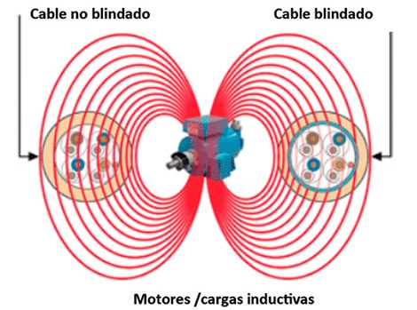
Cables are very often part of the EMI problem. If you have a shielded cable, the connection of the cable shield at the connector is suspect. The termination of the cable shield at the connector and the mating of the connector to the metal enclosure chassis must be well done or the cable will have radiation losses. The shield connection (termination) must be made at 360º on each side of the cable. Pigtail and single side ground terminations are not acceptable. It can be temporarily fixed by using copper tape to close any gaps in the connector area. If this is not possible, aluminum foil should be used to make a temporary shield over the screen, connecting the screen to the box at each end. We must not forget to ensure that the contact surfaces are completely conductive, scratching the paint if necessary. If the cable is filtered but not shielded, make sure the filter assembly is securely connected to the connector housing in the metal box. If you don't have a shielded enclosure, you may have to redesign the TCI. Figure 6 shows the effect of the electric field generated by a radio transmitter on an unshielded cable and on a shielded cable in which the electric field lines do not enter. Figure 7 shows the effect of the magnetic field generated by a radio transmitter on an unshielded cable and on a shielded cable in which the magnetic field lines do not enter. The same is valid in the case of well-shielded metal boxes or enclosures, close in behavior to a Faraday cage, if the length of the openings is conveniently reduced.
Solutions in the enclosures
In armored enclosures or boxes, the main things to consider are openings and penetrations. Cable and connector penetrations have been discussed above. Openings include case gaskets, vents, and displays. Penetrations mainly have ESD issues and these can be located thanks to ESD testing. The discharges in the plastic connectors, switches, the edges of the panels and tactile indicators and displays are the ones that can cause the most problems. A discharge near the slots can affect nearby internal cables. The problem with plastic boxes is very different. Since there is no metal to which the discharge can be applied, the arc can only penetrate through openings in the case. ESDs can go amazing distances to find the metal. In general, the best solution is to prevent discharge from entering internal parts.
To avoid radiated emission and susceptibility, joints and openings must be closed starting with the largest and closest to the cables. The losses depend on the maximum length of the opening and not on its surface. For susceptibility, suspect openings can be checked with portable radio transmitters. For emissions, near-field probes and a spectrum analyzer will help identify field leaks. Depending on the opening, it can be closed with copper tape with aluminum foil. To close the fan openings they may need to be covered with conductive screens or possibly aluminum foil perforated with small holes with a diameter of about 3 to 4 mm. If there are a high number of suspicious openings, it may be better to close all of them, wrapping the entire box, and then go through one by one while evaluating the results. If the display has emission problems, a transparent shield can be used.
Card Solutions
If the equipment does not have external shields, the only option is to analyze the TCI and its cables to the outside. A portable radio transmitter can be used to force faults, especially on power and data cables. Near-field probes and a spectrum analyzer can help isolate the emissions problem, usually by tuning to the problem frequency and then moving the probe around the TCI. The smaller probes are more selective, but less sensitive. Magnetic field probes work best on traces and cables, and electric field probes work best on unshielded connectors. Most emission and susceptibility problems are solved at the boundaries of the TCI and cables, using filters, transient protectors, or their combination. If emissions are the problem, you have the additional option of filtering the power and signals using shields.
Conclusions
Finding the solution to each EMI problem is an uncertain process, and often requires more than one iteration for a single problem, not to mention cases where there are multiple problems at the same time. A methodical approach can make troubleshooting easier. It is important to gather basic information about the problems and the equipment or installation, the preparation of an action plan, the selection of suitable tools, the investigation of the problem, the selection of the most convenient solutions and finally the verification of the performance of the solutions. You must be very methodical throughout the process.


