Security is becoming increasingly important for embedded systems as they evolve from standalone applications to connected applications that store, receive, and transmit data, update with the latest software, remotely monitor, and more. Such requirements are spread across even the smallest implementations, despite limited memory resources and computational power.
Most embedded developers may perceive all of this as too complex to use, starting with crypto-related issues. But in fact, security-related aspects encompass many aspects of chip architecture and software that need to be specifically designed and work together seamlessly to achieve their goals. This article reviews the most relevant aspects to consider in relation to microcontroller security implementations for such small embedded systems.
One of the first steps in ensuring access to a valuable asset is to make it available under a specific use policy. Such a policy could, for example, restrict what part of the application's software can use it and force its use through a defined functional interface that cannot be circumvented, ideally implemented in hardware.
ARM TrustZone technology provides an example of such isolation capability, allowing the user application to be separated into a so-called "secure" and "non-secure" environment within the context of the CPU. But where does the policy apply? At a dedicated "stage", before a memory transaction is propagated to the internal bus (more on this later). In case of violations, an exception is thrown, according to Figure 1:

The application can reactively decide to take an appropriate action, such as restarting a service, logging the event, reporting a fault, etc.
Looking at Figure 1, it's easy to see that unsecured software can access only unsecured resources; How can the two worlds communicate with each other? Fortunately, there is a mechanism to do this. To execute a secure function, the CPU can change its state to secure through a special instruction called a "secure gateway" (SG). An SG instruction is combined with a branch immediately following (ie "jump") to the desired safe function address. When the safe function returns, the processor state changes back to unsafe mode.
Figure 2 provides an example of resource allocation between a secure and non-secure environment:
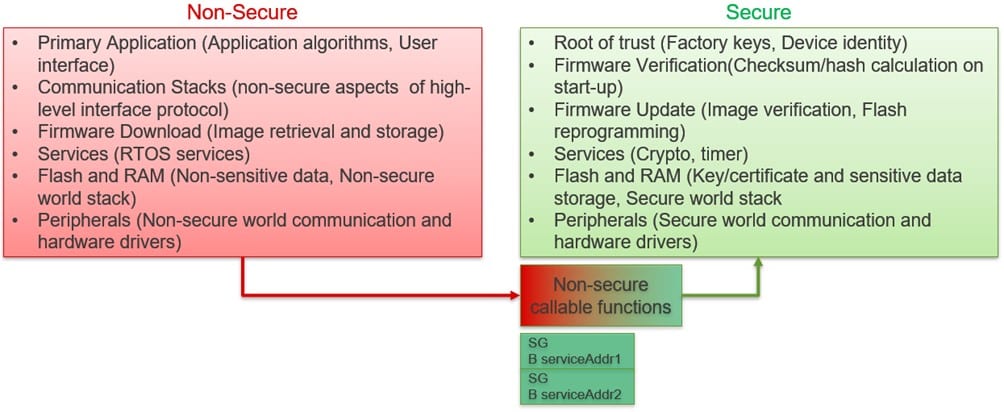
'SG + address' pairs are assigned to a special area defined as unsafe callable; Any parameters such as memory pointers passed by non-safe callable functions can use a specialized "test target" instruction to ensure that a memory buffer is in non-safe memory and does not overlap with safe memory, to prevent data leakage.
While in safe mode, it may be necessary to call back an unsafe function, for example, to notify the calling function of the request status, issue RTOS-related notifications, etc. The compiler will generate the special branch instruction that changes the state to unsafe before the call and sends the return address to the safe stack.
Embedded systems are heavily interrupt driven; when an unsafe interrupt occurs while the CPU is in safe mode, the registers are stacked on the safe stack by default and their contents are automatically cleared. This is to prevent the unintentional leakage of information from the secure area. The partitioning of exceptions within each environment is supported through a dedicated interrupt vector table for each. Similarly, there is a separate implementation of stack pointers, system timers, etc.
This all sounds great, but how do you define those safe memory areas and limits? There are two units that are interrogated in parallel: the SAU (Security Allocation Unit) and the IDAU (Implementation Defined Allocation Unit). On each access to the CPU, both will respond with the security attribute associated with that address. Your combined answer defines the final address attribute, the more restrictive of the two "winners" (a secure region cannot be "overridden" by a less secure attribute). Finally, the result is evaluated against the policy defined as in Table 1. If the access is legitimate, you can continue; otherwise, it is blocked and a safe exception is thrown.
Notably, the configuration of the SAU (how many regions are supported, default settings, etc.) can be defined at design time, and the implementation of the IDAU is defined, ie left to the device manufacturer.
Memory Protection Units (MPUs) within each domain will protect individual threads from each other, improving the overall robustness of the software. Figure 3 shows an example partition on a TrustZone-compliant microcontroller:

Have we achieved any safety-related goals so far? Actually, not yet. TrustZone can isolate safe from unsafe threads of your application, but it does not provide any "security" per se and cannot enforce legitimate access; rather it prevents unwanted use or direct access.
The developer must decide which parts of the application will be isolated; TustZone can be useful and cannot be bypassed in software (compared to a classic MPU), so routines related to cryptographic operations are a good candidate. In either case, the system will apply the TrustZone settings from the start of execution and will avoid tampering with these limits (for example, by storing them in a memory area that the CPU cannot directly modify).
Good practice suggests keeping the amount of functionality implemented within the secure environment to a minimum. This reduces the possibility of bugs, runtime errors, and malicious exploitation of any software flaws. As a side effect, functionality validation becomes much lighter during debugging and testing.
What cryptographic resources must be provided by an MCU? It depends on the complexity of the application; for an entry level solution, a pure software routine might suffice. But hardware support of cryptographic algorithms reduces power consumption and code size, at higher execution speed.
That being said, the first building block of most cryptographic protocols is a TRNG (true random number generator), which must be validated and tested for its entropy properties and quality of randomness (since a poorly constructed RNG can mess up the security of any algorithm). use it).
For local storage, support for symmetric algorithms like AES with multiple modes of operation is almost mandatory to encrypt and decrypt most data. In combination with hash algorithms ("cryptographically secure checksums") such as SHA-2 or SHA-3, the application can perform simple authentication checks and verify that the data content has not been modified.
For advanced connectivity, asymmetric encryption algorithms such as RSA or ECC can support identity verification on client/server connections, help obtain ephemeral session keys, or verify the origin and legitimacy of a firmware update. Such accelerators will also be able to generate keys on the chip, for local use.
But the really difficult problem is key management, since keys have to be kept confidential, whole and available. Many scenarios need to be considered: when the key is injected (stored) in the MCU, how to transport it, how to load it into cryptographic hardware, and how to protect it from leaks.
Ideally, the application will never handle key material in clear format, to avoid dangerous exposure. An easy way around this is to handle it within the secure area of the TrustZone, but best is within a dedicated isolated subsystem on the chip. Once the keys are stored in non-volatile memory, techniques such as key "wrapping" (key encryption) help protect privacy. Making the packed data unique to each MCU further mitigates key leakage risks and eliminates cloning threats. For such a mechanism, a "root of trust" for storage is needed, in the form of a unique "key encryption key" for each MCU, to ensure that no specific device is compromised and allow a "class" attack on all similar units.
DPA and SPA attacks record and analyze power consumption traces to reverse engineer the key value. These are getting cheaper and faster to implement, even for not highly skilled attackers with limited resources. If physical access to the device is a concern, without other means of access control in the system, countermeasures against those threats are required within crypto engines. Also, any monitoring of signals connected to the equipment case, which can notify the MCU and possibly take a timestamp of the tamper event, will be highly desirable.
The isolated subsystem will allow a user to provide chosen keys on the device and have them safely wrapped and stored, ready for later application use. The MCU must support some interface to do this both in the field and in the factory, allowing for easy initial production and later upgrade in the field. Such passages must be secured and not expose any key content during transit.
In modern MCUs, other functional entities can autonomously transfer data to and from memory or peripherals, to improve performance and use available bandwidth efficiently. Some examples are DMA engines, graphics drivers, ethernet drivers, etc. It is vitally important that the MCU can set the security attributes of such agents and implement specific "access filters" on communication points, such as memories and memory-mapped peripherals.
Any processor is useless without signal input and output capability. Protecting such interfaces from misuse is a fundamental requirement to prevent tampering, as this is the natural way to interact with the MCU. The cautious designer should verify that the MCU can restrict access to secure I/O ports and peripherals, thus preventing software from “taking over,” interfering with, or maliciously snooping on communication, while isolating the ports and peripherals from one another.
During development, to test the software, a Jtag-based debugger is almost mandatory. Such an interface can access most on-chip resources and is therefore a critical backdoor for any application deployed in the field. The use cases for securing Jtag are very different: block it permanently or maintain debugging ability in the field, to protect access. Whichever strategy is chosen, the protection will not allow it to be circumvented, enforcing proper authorization via an authentication key and granting access only after successfully completing a challenge-response protocol. Finally, the device must support and secure the mechanism to return the device to the factory in case of defect analysis, possibly erasing any stored secret assets while keeping the interface secure until reaching its destination.
The final application image, once deployed to the field, may need to be made immutable in parts, to ensure that it is in a known state at all times. To support this requirement, the microcontroller must have the ability to permanently protect user-defined portions of non-volatile memory from modification.
Last but not least, each microcontroller undergoes a lengthy testing process before shipment; many of these test results (trim values, production specific data, etc.) and other settings are stored on the device. This special test mode, while not significant to an end user, can access, control, and potentially alter all of the chip's resources. The manufacturer must ensure that such a potential backdoor cannot be opened maliciously or by mistake once the device leaves the factory and is in the hands of the customer.
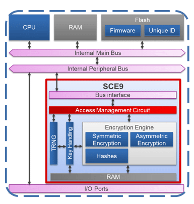
Searching for a microcontroller that supports the above requirements can be a daunting task. Fortunately, Renesas designed the RA series of microcontrollers with exactly those goals. The RA6 and RA4 series include devices with an ARM Cortex-M33 CPU with TrustZone and secure MPUs. They allow safe limits to be programmed for all types of onboard memory easily and simply. They incorporate Secure Crypto Engine, a cryptographic subsystem (Figure 4) that provides secure element functionality with higher performance and lower cost of materials. The SCE includes state-of-the-art cryptographic accelerators, a TRNG, supports key generation, key injection implements SPA/DPA countermeasures, and a hardware unique key as root of trust. Its DMA controllers, bus masters, peripherals, I/O ports have dedicated security attributes and tamper detection functionality is implemented. Integrated device lifecycle management handles secure/non-secure debugging, scheduling, supports return-of-material procedures, and secure test mode. Non-volatile memories can be permanently block protected at the user's choice. For more information on the security features of the RA family, visit the Renesas website.
Author: Giancarlo Parodi, Principal Engineer, Renesas Electronics


