Author: Rolf Horn – Applications Engineer, DigiKey Electronics
Radar has become indispensable for countless applications, such as military surveillance, air traffic control, space missions, and automotive safety. One of the most challenging situations for designers is that of long-range radars, where the return signal is extremely weak, ambient and circuit noise degrades the signal-to-noise ratio (SNR), and pulse rolloff becomes a problem.
Although gallium nitride (GaN)-based power amplifiers (PAs) offer significant efficiency and other advantages over devices using older processes, designers must take a system-level approach to minimize pulse decay and its effects. This will ensure superior performance in long-range radar systems.
This article briefly reviews radar operation and examines the problem of pulse decay. A state-of-the-art S-band GaN PA is then presented. Analog Devices and an accompanying evaluation board and suggested tactics to compensate for and minimize boost statism.
Principles and problems of radar
The principle of radar is simple: a system transmits a short on/off pulse of radio frequency energy, and a receiver picks up the signal reflected back from the target. The time elapsed between the transmitted pulse and its echo determines the distance (range) to the target, since both propagate at the speed of light.
Although this simple pulse is sufficient in principle, it is inadequate for the real world of multiple targets, especially at distances of tens, hundreds, or even thousands of kilometers. These long-range radar systems face two problems:
- The return signal from a distant target is very weak and the SNR is poor.
- Distinguishing between multiple targets at a distance requires resolving echoes that are very close to each other, assuming their return signals have not been distorted and overlap.
The signal strength is very low due to the inevitable physics of the situation and the rule of 4ª power. This is demonstrated by the classic radar equation that relates radar performance factors and practical effects:

Where:
- Pr is the expected reception power
- Pt is the transmission power
- Gt is the antenna gain
- Gr is the receiving gain
- λ is the radar's operating wavelength
- σ is the effective cross section of the target
- R is the range from the antenna to the target.
The equation shows that round-trip attenuation primarily determines range loss, since R, raised to the fourth power, is in the denominator.
The obvious way to overcome range loss is to increase the peak power of the transmitted signal and lengthen the pulse to increase its total energy. However, this approach blurs the return and introduces overlap to the point where multiple objects appear clumped together (Figure 1).
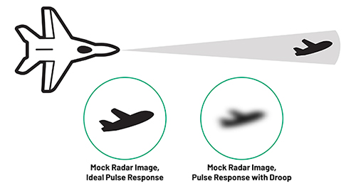 Figure 1. These radar image sketches show an ideal impulse response (left) and a degraded impulse and range response (right). (Image source: Analog Devices)
A more sophisticated way to improve performance is to shape, modulate, and "compress" the transmit pulse to improve range resolution and SNR. Pulse compression allows the radar system to resolve multiple targets in a tight cluster rather than seeing them as blurry, overlapping return pulses at the receiver.
Problems and solutions for falling pulsed energy
Although it is possible to increase the pulse energy, this creates other problems. One of them is that higher energy exacerbates the AP-centered pulse decay phenomenon (Figure 2).
 Figure 2. This nominally rectangular radar pulse shows overshoot, pulse width, rise/fall times, and rolloff (Image source: Analog Devices).
Pulse rolloff is the unwanted reduction in pulse amplitude from start to finish, typically characterized in decibels (dB). This reduction decreases the range over the pulse length, since the combination of pulse amplitude and width determines the radar's range as an integrated power level.
The drop occurs even when using efficient solid-state GaN PAs such as the ADPA1106ACGZN from Analog Devices. This 46 decibels per milliwatt (dBm) (1 watts) device, with a power-added efficiency (PAE) of 40% over a 56 gigahertz (GHz) to 2.7 GHz bandwidth, is ideal for the pulse power requirements of S-band radar systems.
What causes momentum to drop?
The fall is mainly due to two different mechanisms:
1: PA performance se is disturbed by the sudden impulse current. This introduces dissipation and other thermal effects that cause critical device performance parameters to shift. As the GaN PA transistor channel temperature increases due to Joule self-heating, which is the product of current density and electric field, the amplifier output power decreases. Figure 3 illustrates the relationship between channel temperature, drain current, and drain voltage for a GaN transistor operating point with a pulse width of 100 microseconds (µs).
 Figure 3 shows the relationship between channel temperature, drain current, and drain voltage for a GaN transistor operating point with a pulse width of 100 µs. (Image source: Analog Devices)
Although GaN devices are relatively efficient, some power is lost as heat, so effective thermal management is required to achieve the best results. Depending on the pulse width, pulse repetition frequency (PRF), and duty cycle, a combination of one or more cooling methods will be required, such as fans, heatsinks, cold plates, or liquid cooling.
As the duty cycle increases with a constant pulse width, the time the PA spends off between pulses decreases. This means the PA has less time to cool down and is at a higher temperature on the rising edge of the next pulse. In the limiting case of a 100% duty cycle (continuous wave (CW)), there is no time for the PA to cool down, and its temperature remains constant at its maximum.
This leads to a compromise. As the duty cycle increases, the average part temperature increases, reducing the maximum and average power output. However, the magnitude of the temperature rise during the pulse decreases, meaning there is less droop and more consistency across the pulse width. Therefore, the compromise becomes a balance between less droop and more power.
2: The second consideration is the power supply.Due to the rapid transient nature of pulsed power, the PA power supply faces the challenge of handling sudden high-power demands while maintaining the voltage rail at the required value. As with the thermal problem, solutions are known, but implementation is critical.
It begins with the addition of large charge storage (bulk) capacitors along the PA bias line and the placement of ceramic or tantalum bypass capacitors nearby. This is seen on the evaluation board. ADPA1106-EVALZ (Figure 4, left) which has decoupling capacitors placed close to the amplifier, and its associated “push-button board” with large charge storage capacitors that maintain power levels over wide pulse widths (Figure 4, right).
 Figure 4. The top of the ADPA1106-EVALZ evaluation board (left) shows the unique arrangement and adjusted position of the decoupling capacitors; the bottom shows the aluminum header spacer (center); the associated pushbutton board contains the high-value bulk capacitors used to supply the necessary current during pulse transients (right). (Image source: Analog Devices)
The evaluation board is designed to address the unique challenges of optimizing the ADPA1106 application. It comprises a two-layer printed circuit board (PCB) fabricated from 4350-mil Rogers 10B copper-clad board mounted on an aluminum heat spreader. The spreader provides thermal relief for the device and mechanical support for the PCB. Mounting holes on the spreader allow it to be attached to a heat sink. Alternatively, the heat sink can be clamped to a hot and cold plate.
Although the use of large storage capacitors is not ideal, as they increase the size, weight, and cost of the radar assembly, they are often the only viable approach. Furthermore, the relative position, orientation, and type of decoupling capacitors used near the amplifier will influence their effectiveness and pulse fidelity. At RF frequencies in PAs such as the ADPA1106, the impact of parasitic capacitance and inductance must be carefully considered and included in the design.
Decay results as a function of pulse width and repetition rate
The ADPA1106 PA was subjected to decay testing in two ways: by varying the pulse width with a constant pulse repetition frequency, and by varying the duty cycle while maintaining a constant pulse width. In both tests, the pulse decay was measured from 2% of the pulse period to the end of the pulse to eliminate the effect of initial overshoot.
The first test uses a variable pulse width at a fixed pulse repetition rate of 1 millisecond (ms) (Figure 5). There is a high correlation between increasing pulse width and increasing droop. At the maximum pulse width tested, droop approaches 0.5 dB, which is the maximum droop level typically acceptable at the system level.
 Figure 5. Tests with a fixed pulse repetition rate of 1 ms show the correlation between increasing pulse width and increasing pulse decay. (Image source: Analog Devices.)
Furthermore, due to thermal effects, peak and average output power decreased slightly with increasing pulse width, while the downward slope in the longer pulse width tail increased slightly. This may indicate that self-heating effects are beginning to affect the thermal management of the package and the heatsink underneath.
To evaluate the effects of duty cycle, the ADPA1106 was tested again using a constant pulse width of 100 microseconds (µs) while changing the duty cycle (Figure 6). As the duty cycle increases toward 100%, the PA has less time to cool between pulses and is at a higher temperature on the rising edge of the next pulse. As a result, the average part temperature increases, the pulse amplitude decreases, and the magnitude of the temperature rise during the pulse decreases.
 Figure 6. Using a constant pulse width while varying the duty cycle shows that the change in magnitude decreases as the duty cycle increases. (Image source: Analog Devices)
This demonstrates the trade-off. It shows the negative impact of reduced peak and average output power due to the higher absolute temperature of the part. However, the advantage is less droop and greater consistency of output power across the entire pulse width, since the temperature change of the PA is smaller over the duration of the pulse.
Conclusion
Achieving maximum range in radar systems requires a system-level approach to minimize pulse droop. This includes effective thermal management and the incorporation of massive capacitors into the power supply. To demonstrate how to balance the necessary trade-offs, this article uses real-world test data with the ADPA1106 high-efficiency PA to evaluate droop by varying two critical pulse parameters and using appropriate cooling. The results showed that the device offered very low droop, less than 0.3 dB, over a typical range of pulse conditions.
Source: https://www.digikey.es/es/articles/how-to-maximize-range-in-radar-systems-based