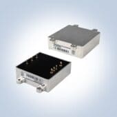
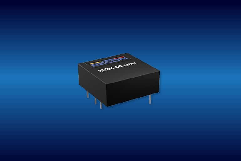
A DC-DC converter is an electronic control unit (ECU, Electronic Control Unit) that converts an input voltage from one level to another. To ensure DC-DC ECUs run smoothly, manufacturers have to put them through rigorous functional testing before they leave the manufacturing plant. These tests typically include power input and load output simulations to measure the stability and integrity of voltage outputs, energy efficiency, etc. Levels can go from low to high power. Higher power DC-DC converters are often used in automotive applications, with ranges exceeding 200 W. DC-DC converters are used in start-stop systems, which automatically stop the combustion of the automobile engine while it remains stationary, causing the engine to restart only when the driver steps on the accelerator. These systems are becoming more widespread, thanks to the industry's effort to create greener environments by reducing carbon emissions.
Functional tests of DC-DC converters
DC-DC converters are used for cabin comfort, maintaining a 12V source that prevents any interruption to the infotainment or ventilation systems during engine start. Figure 1 shows a simplified block diagram illustrating the operation of a typical DC-DC converter ECU during power up. Whenever the battery voltage drops below 12V due to pulse start, a trigger signal is sent to the ECU which increases the voltage and maintains it at a constant output level of about 12V.
Simulation of conditions
To carry out the functional tests of the DC-DC ECUs, a battery input emulator capable of generating arbitrary high power input waveforms in the ECU is required. Manufacturers often define their own boost input pattern. Figure 2 provides an example of an emulated voltage pulse input for testing purposes. A high power dynamic DC power supply is also needed to create an arbitrary voltage pattern with a high inrush current to simulate the transient condition of the battery in the test process. To achieve the proper functional test scenario, we will need dynamic DC power supplies capable of generating 12 to 6 V pulses with a 1-2 ms decay time, conforming to the requirements of most transient response emulations. of automotive batteries. It is also important to choose the right power supply to minimize initial setup costs. There are instruments on the market, such as the Keysight N7951A/N7971A power systems, with options of 1 and 2 kW at 20V nominal, which allow you to choose between low (<300W) or high power (>300W) ECUs. In this way, we will enjoy greater flexibility to adapt to different power needs with the same equipment. In addition to input emulation, electronic or passive loads are needed to simulate the effects of electronic networks on board vehicles. A load switching solution allows loads to be flexibly connected and disconnected to establish open/closed loop circuits for functionality testing. The solution must also be able to handle high current handling for automotive applications. Test engineers often have to develop custom switches for load connectivity with safety circuitry in mind to protect against ECU failure. Especially in the high mix automotive manufacturing sector, custom switches have to be frequently redesigned to accommodate different ECU applications, which takes time and money. Thus, it is usually more cost effective to have a standard load switching solution. Some vendors, such as Keysight, offer such commercial solutions, capable of withstanding many hours of high current operation up to 40A per channel, a common requirement in automotive manufacturing testing.
Energy efficiency measure
In general, energy efficiency is defined as “energy efficiency = VIout/VIin x 100%”, where VIout and VIin are the output and input power consumptions, respectively, of the ECU. Thus, a higher efficiency will imply a lower power loss during the conversion. Power analyzers are very useful for engineers who want to quickly measure AC/DC power consumption, efficiency, and quality. Multichannel analyzers can measure input power and output power at the same time with great precision. However, it may not be necessary to use a high-precision instrument on the production line, since performance testing does not require as much accuracy and speed for analysis or characterization during the design phase. Additionally, functional validations typically test operation only at critical levels. Figure 2 illustrates typical levels tested on phases A, B, and C of a drum input signal. A digital multimeter (DMM) can be used to measure input and output voltages and currents when they are static. The voltage measurement is relatively easy to capture by probing the ground reference of the inputs and outputs. To measure current, instead of using the DMM as an “ammeter”—something that only works for low current measurements—a current shunt method is used. A current transducer or resistance sensor is placed in series at all inputs/outputs; then we use the DMM to measure its differential voltage, which we then convert to current using Ohm's law: V = I x R. Finally, energy efficiency can be calculated using the voltage and current results from the inputs/ Departures. Keysight's TS-5000 load switching solution offers current sensing capability. Load cards are incorporated with each resistance sensor or current transducer on each channel to measure current. The architecture of the Load Cards and Matrix Switches allows them to be interfaced with a basic and inexpensive DMM, thus offering a much cheaper to manufacture solution for DC-DC energy efficiency measurements.
Stability measure
It is necessary to validate the stability to guarantee the good state of the DC-DC converter during activation. A dynamic DC power supply is programmed to generate battery pulse patterns. A digitizer then captures the pulse patterns to verify the desired upload and download speeds. In addition to input validation, the digitizer is also used to measure stability
output. The voltage output waveform is acquired during ECU activation. The full waveform illustrates the overall stability of the output: ripple, average, peak-to-peak, and rate of stabilization through Boost mode. It is recommended to use a digitizer with a minimum sample rate of 0,1 us; this high resolution setting will help capture any glitches or sudden spikes. Automotive batteries typically run at around 12,6V, so the digitizer must be able to detect input signals at >10V. Higher power DC-DC converters often have multiple inputs/outputs, and you'll need a digitizer. with more than two channels to measure all inputs and outputs simultaneously. Input and output waveform acquisitions should be synchronized to the same time sequence, showing correlation between all inputs/outputs and reducing overall test time. Keysight's M9217A/ L453xA digitizers have options of two or four isolated input channels for simultaneous measurements. The high input voltage at ±256 V also eliminates the need for input signal attenuation for typical data acquisition instrument with a dynamic range of ±10 V. In the case of DC-DC converters with multiple inputs/outputs, the number of channels in the digitizer can be multiplied by configuring additional digitizers within the system, while synchronization can be achieved thanks to its triggering capabilities. This scalability allows the user to update the solution with the existing configuration without having to migrate to another instrumentation.
Conclusion
The cost of testing is one of the key factors when calculating the total cost of manufacturing an ECU. Automotive manufacturers often spend time developing their own stackable rack test systems, and may end up spending more to purchase expensive instruments. Total costs can be greatly reduced by choosing the right instrument or using the right testing methodology. Choosing cost-effective instrumentation and load switching solutions with commercial test software as a foundation can help improve the competitiveness of manufacturers in the automotive industry while keeping costs reasonable.