Wendy Preston, Technical Author, harwin
The extreme levels of temperature and humidity often found in industrial facilities put considerable stress on electronic components and can cause equipment to malfunction. Components are also subject to shock, vibration and the risk of liquid ingress due to their environment. Sometimes they are outside the equipment and this means that they are directly exposed to adverse conditions. Finally, torsion forces, mechanical stress, and continual connection/disconnection activity can affect performance. Therefore care must be taken when selecting connectors and cabling for industrial applications and shortcuts must be avoided. This article reviews the top concerns for industrial applications and highlights test procedures that should be considered.
Main selection criteria
High temperatures are often a concern when connectors are integrated into industrial equipment as the processes carried out can generate large amounts of heat. Under these circumstances, connectors that resist a wide range of temperatures should be chosen. The tests according to EIA-364-32C Condition III can certify the validity of the connectors to assume extreme temperatures. In this test, the connectors are subjected to thermal cycling between -55°C and +125°C a total of 10 successive times.
Problems with connector resilience against vibrations can arise in most industrial installations due to continuously running motors and drives. EIA-364-28D Condition IV tests can be used to assess how well connectors can withstand vibrations. During this test procedure, the devices are subjected to vibration frequencies from 10Hz to 2000Hz with a vibration amplitude of 1,52mm to verify that there is no interruption in the electrical connection. The test is carried out over 12 hours and 4 hours are assigned to each directional axis.
Other mechanical stresses are the resistance of the cables against jerks and their disconnection due to the forces present. To prevent this from happening, some type of strain relief can be incorporated into the cable assembly. The use of connectors with SMT fixing brackets increases the contact surface of the assembly with the printed circuit board, thus allowing the connectors to withstand higher tensile forces. When the cable assembly needs greater protection against strains, the best solution could be the "backpotting" technique, which consists of applying an epoxy resin compound on the back of the connector to better fix the cables. If repetitive motions are involved or space is limited it might be preferable to use flexible printed circuits instead of conventional wiring. Flexible printed circuits are much thinner and therefore more suitable for low profile installations and in tighter or more dynamic curvatures.
The durability of the connector joint is another factor to consider. If cables are repeatedly disconnected and reconnected, their specifications should include their use for numerous operating cycles. If not, their replacement could be very expensive and uncomfortable.
Connectors are at risk of being damaged when operators cannot see the connection and have to work blindly. To counteract this, connectors should incorporate polarization and plating mechanisms. The design can incorporate generous ridges on the male and female elements of the connection to help guide them. Coating these connectors will allow them to ensure that they are properly aligned and fully bonded. Before deciding which connectors to use, it is important to ascertain what characteristics it has to avoid incorrect union. It is also worth assessing whether the connectors allow a certain angle of misalignment when starting the joint.
The selected locking mechanism is very important as it must be firm enough to prevent connectors and cables from accidentally coming loose. At the same time, it must be quick and easy to use so that all necessary wiring connections can be made in an acceptably short time by the operator.
How to find an optimal solution
It is clear that there are many factors to consider when choosing connectors and cabling for industrial applications, so it is vital to have a good understanding of the electrical, mechanical and environmental characteristics before beginning the selection process.
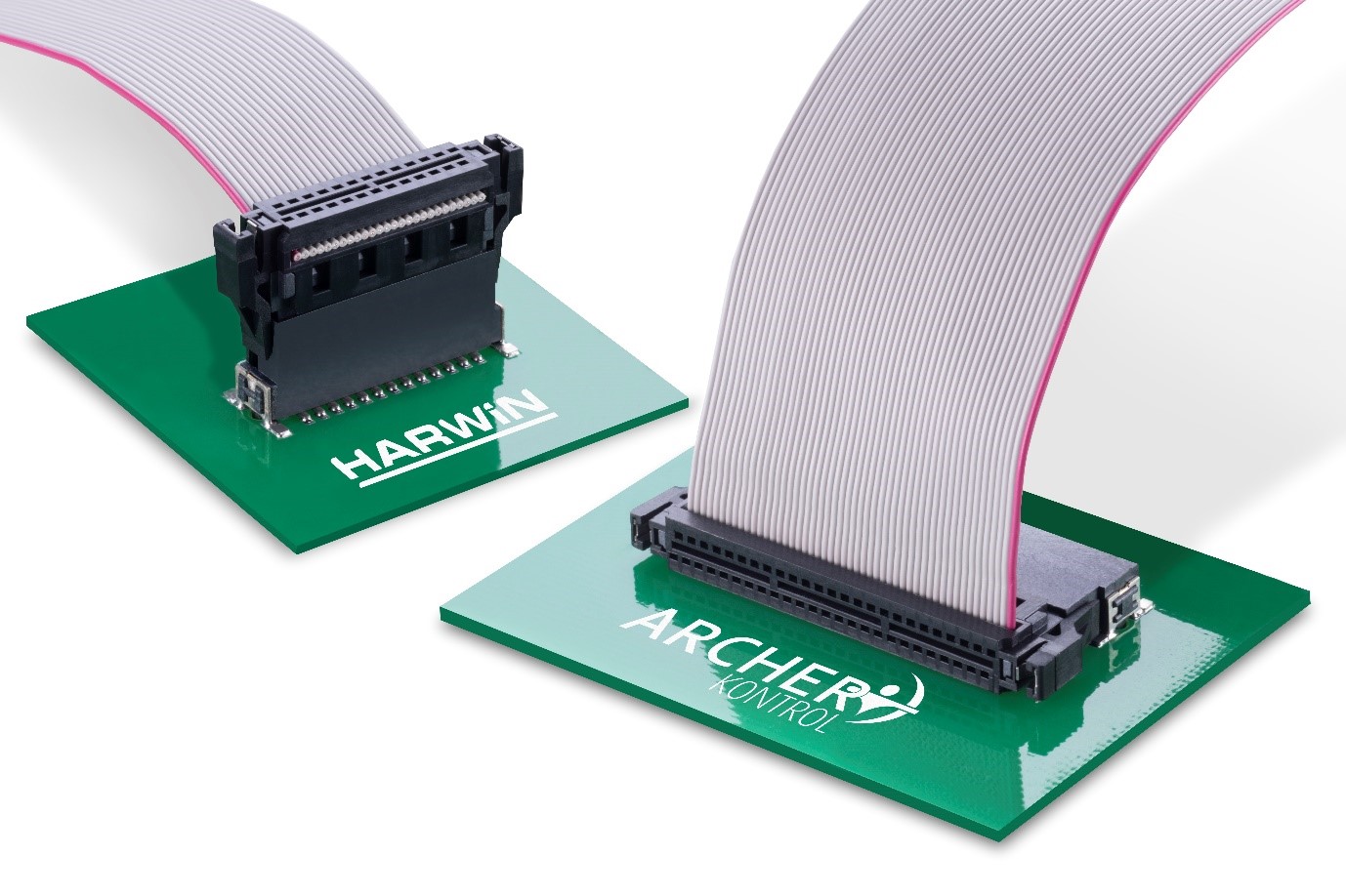
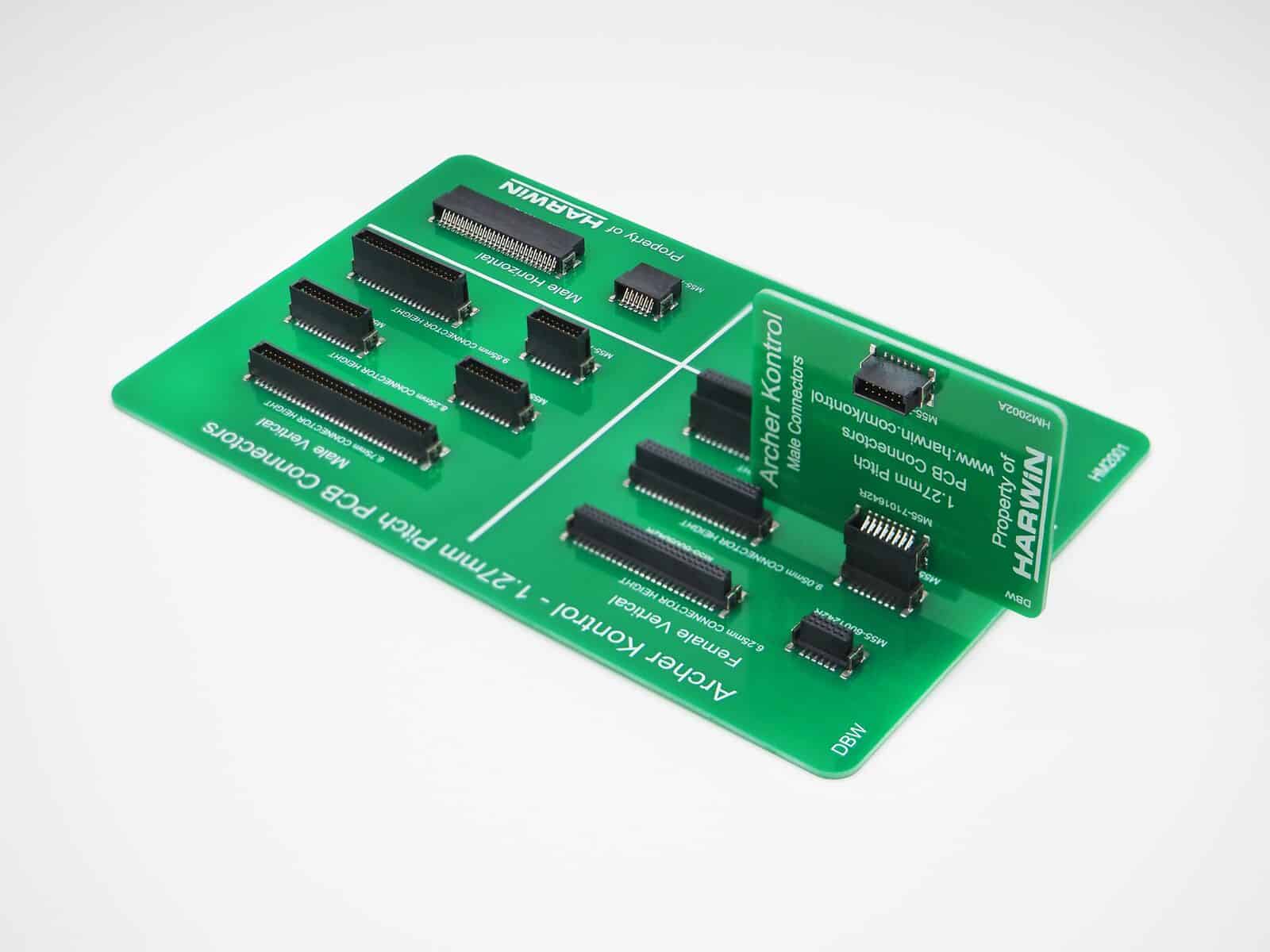
Harwin developed its Archer Kontrol series to address the many challenges posed by harsh industrial environments. Available in 1,27-12 contact configurations, these 80mm pitch connectors achieve impressive performance parameters. Each contact can carry currents of 1,2A and achieve data transmission speeds of up to 3Gbps. The jacketed design (with built-in bias) protects every contact.
Archer Kontrol connectors can be supplied as parallel board-board, edge-edge and right angle configurations. Versions with different stacking heights are available to accommodate high-density PCBs. These connectors can be accompanied by off-the-shelf or custom-designed cabling products, depending on the application requirements.
Archer Kontrol connectors can withstand temperatures up to 125°C and have been tested in accordance with the thermal shock requirements of EIA-364-32C Condition III. They also fully comply with the EIA-364-28D Condition IV vibration standards. An insulation resistance of >1000MΩ prevents flashover. Finally, a retention force of at least 3,9N per contact and a bond durability of 500 cycles ensure long-term operational integrity.
Selecting custom cabling products and connectors for industrial applications can be a complex process with several potential pitfalls. If the different elements described in this article are taken into account, finding the ideal connector for various industrial-type applications will be a much easier process.


