
Today, virtually any embedded design requires a display. However, the selection and integration processes present challenges for developers and lengthen the development phase. Mass-produced smart display modules are often an affordable alternative.
Article written by Nikolai Schnarz, Corporate Product Sales Manager Displays, and Gintaras Drukteinis, Technical Support Engineer, both from Rutronik
When comparing a discrete design to a display module, the modular approach doesn't seem particularly appealing at first, when the total cost of materials is considered. However, when you factor in the speed at which development can be completed and the ease of use, the module comes out on top. For example, an existing application running on an 8-bit microcontroller (MCU) must now have a full-color graphical display with a touch interface. Although many MCUs are capable of connecting to an LC display via an integrated or discrete controller, the actual size and resolution may be limited by the MCU's resources. So an 8-bit MCU can drive a two-line dot-matrix display, but the processing resources are often not enough for larger screens. Also, the designer has to add embedded software such as libraries and image files. Adding touch functionality requires even more development effort. During the production phase, a strict inspection of the new display must be carried out, as there is always the possibility that something has been changed without prior notice, which requires optimization or redevelopment of the display drivers.
What the modules contribute
Smart modular displays usually have a standard interface, such as I²C, SPI or UART, for communication tasks with the host (host). Some also include an embedded microcontroller that is not only responsible for all the graphical elements, but also has a wide variety of I/O and other peripherals, thus ensuring that the module can run the entire target application.
Many modules are supported by a library of functions, which ensures that they can be controlled relatively easily by the host MCU. Some of them also have an integrated development environment (IDE) with advanced capabilities including design and creation of a graphical user interface (GUI) as part of the embedded design process. To support rapid prototyping and application development without having to write a line of code, some of these IDEs offer workflows. WYSIWYG (what you see is what you get – what you see is what you get) with “drag and drop” function (drag-and-drop).
So the beauty of the modular approach is that all the controllers and the primary and GUI functions have already been developed and tested. Therefore, engineers can fully focus on the actual GUI design. The host MCU can offload all display tasks to the module, which means that all its resources are available to the main application.
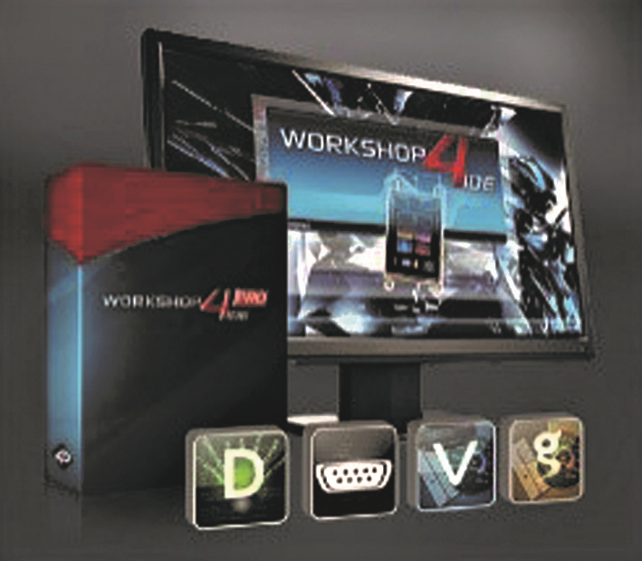
Figure 2: The Workshop4 IDE tool offers developers numerous GUI design options. Source: 4D Systems
UI design support
In order to also support the GUI design, the display manufacturer 4D Systems has developed a tool to create intelligent graphical user interfaces in the fastest and easiest way possible. Workshop4 IDE offers various programming development environments, from text-based to visual (Fig 2). Its drag and drop functionality is also intuitive to use, eliminating the need for traditional coding.
Display module for the Rutronik RDK2 Development Kit
Thanks to these advantages, Rutronik also uses a smart display module in its Development Kit RDK2 (Fig 3). It mainly supports the development of a proof of concept for various application areas, such as IoT and IIoT, devices w smart and smart homes (home automation).
The card is based on the high-performance, ultra-low-power microcontroller CY8C6245AZI-S3D72 de Infineon. In addition, the RDK2 features an external NOR Semper flash memory of 512 Mbits and a PSRAM AP memory of 64 Mbits APS6404L-3SQR-ZR connected via a QSPI interface. In this way, the capabilities of the RDK2 are increased when it simultaneously uses these memories in a memory-mapped mode (memory-mapped).
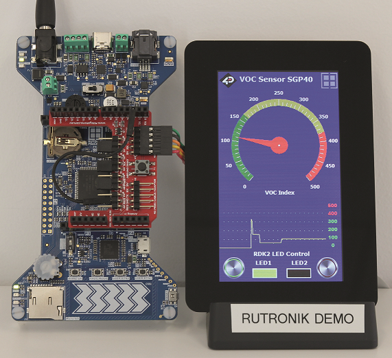
Figure 3: Rutronik's RDK2 Development Kit with an intelligent display module. Source: Rutronik
The 4.3” display gen4-uLCD-43DCT-CLB with integrated capacitive touch panel is used as a display and input medium for an application example of the RDK2, which determines the air quality using the VOC index (volatile organic compounds). It is based on the graphic driver DEVIL16 and is managed by the UART interface. Your data rate of 115.200 bit/s it is sufficient to operate the touch panel without a perceptible delay. However the UART data rate can also be increased to 600 kbit / s, if necessary.
We recommend the Arduino adapter 4D-ARDUINO-ADAPTOR-SHIELD-II to ensure fast integration with RDK2. Firmware example RutDevKit-PSoC62_GEN4_ULCD_43 refers by default to VOC sensor data SPG40 de Sensirion, but can also be automatically switched to the built-in potentiometer POT1 if the sensor is not recognized by the I2C bus. The potentiometer is read through the periphery of the ADC. Subsequently, the ADC values are shown on the display. The card RAB1 – Sensorfusion with a SGP40 sensor will also be available from Rutronik.
For visualization tasks, 4D Systems offers the code library ViSi Genie. Included in the RDK2 sample project RutDevKit-PSoC62_GEN4_ULCD_43 for use in the IDE ModusToolbox, a useful collection of software and tools for rapid development with Infineon MCUs. In order to enable the code library, user API configuration functions and event handlers are implemented. They allow developers to control what should happen in the program when a specific event, such as an input, occurs.
The function prototypes that must be implemented to ensure that the ViSi-Genie stack can actually run are shown in the "required functions" box.
The display is controlled by sending messages to individual objects on the screen or to background objects that may not be visible. For example, the command that updates the angle gauge with the VOC index might look like this:
/* Update the VOC Index gauge */genieWriteObject(GENIE_OBJ_ANGULAR_METER, 0, gaugeVal);
Events, such as keystrokes, are received at regular intervals of 20 milliseconds or faster when this function is executed:
/* Check for events */genieDoEvents(true);
The Workshop4 IDE allows developers to design graphic objects and program them into display memory. The sample app tests the basics using an angle gauge and a scope gadgets to display the VOC index. The angle meter refreshes every 50 milliseconds, while the scope it does so every 10 seconds, making it possible for users to simultaneously monitor current and previous VOC index values.
The firmware example for RDK2 and the IDE Workshop4 IDE project are available for download on the Rutronik website.


 Now In Stock At Mouser")