This article explains how built-in and stand-alone analog functions differ in design and testing, and what this means in terms of specifications, device variations, and robustness. Since analog functions are so diverse and the A/D converter (ADC) is the foundation of any mixed-signal design, we will focus on ADCs.
Today's complex distributed systems acquire and analyze more analog data as well as offer monitoring and diagnostic capabilities. As these systems become increasingly complex, the need to accurately measure analog signals continues to grow. To best meet these precision requirements, designers are often faced with the choice between a microcontroller with an integrated ADC or a stand-alone ADC. So what differentiates an integrated ADC from a standalone one and which one is best for your application?
Let's first study the performance of stand-alone and embedded ADCs to determine how the right choice can be made for each application.
Integrated ADCs: Performance Factors
process technology
Let's look at the ADC from the point of view of the semiconductor integrated circuit used in the design of the integrated ADC. Since the ADC is a peripheral of the microcontroller, the designer of an embedded ADC will tend to use a process suitable for the microcontroller, such as a 28-nanometer process that offers good digital density and high-speed transistors for the microcontroller. While a reduced geometry process like this could also decrease the size of the ADC, there are several factors to consider:
- The relative cost of the ADC will be increased due to the substantially higher cost of the process.
- The size of the components available in the process will increase the inherent noise of the ADC, and specifically the thermal noise or kT/C noise.
- Larger capacitors that reduce thermal noise in ADCs will significantly limit the use of processes with smaller geometries (from a geometric point of view it is more difficult to implement the components necessary for analog performance in smaller geometries).
- The capacitors smaller geometries will increase leakage and affect the linearity of the design.
- The adjustment of elements not as controlled as in processes with larger geometries such as 90 or 180 nanometers will lead to a lack of control in the manufacturing process and will cause variations in the performance parameters of the ADC.
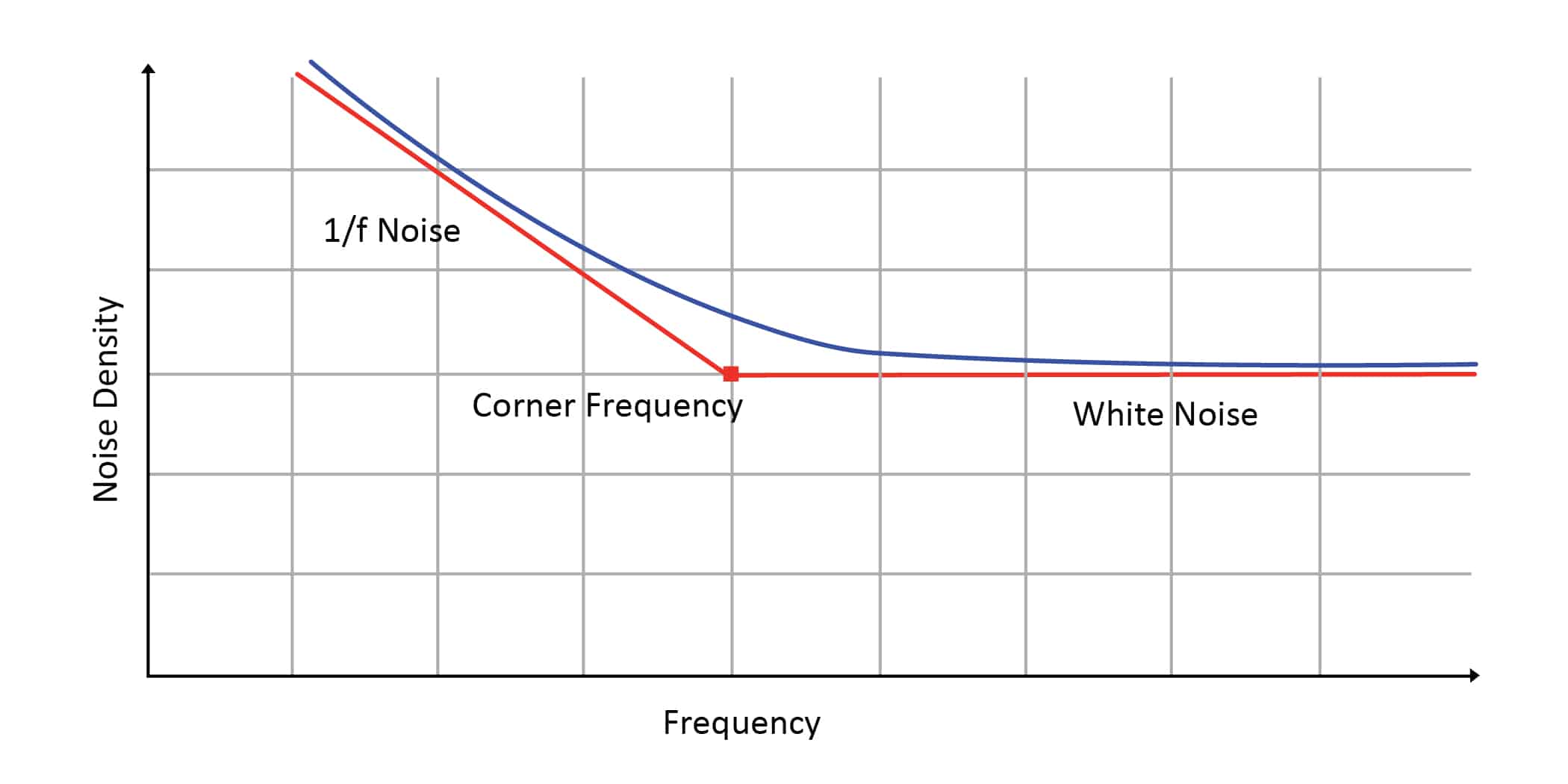
Another difficulty with small geometry processing is 1/f noise. The 1/f noise is dominant at low frequency and decreases from DC by approximately a factor of 1/square root (frequency). At higher frequencies it is the white noise that begins to dominate the 1/f noise at a point called the cutoff frequency as shown in Figure 1. If a designer wants to improve performance using digital compensation techniques such as averaging or oversampling, they have Make sure you only sample values that contain white noise and not 1/f noise.
The problem for processes with smaller geometries compared to larger geometries is that the cutting frequency is significantly higher. This explains why digital filtering techniques, such as averaging or upsampling, do not improve system performance on systems with high 1/f cutoff frequencies. In fact, in some cases, digital filtering techniques can reduce system performance. The bottom line is that the limitations of the process will ultimately determine the performance that the ADC can achieve.

1/f noise is present at low frequencies and exceeds white noise around the cutoff frequency.
integrated circuit layout
If the microcontroller is placed on the IC close to the ADC, the ADC's analog performance will be affected in two ways:
- The fast-switching microcontroller will introduce switching noise and ground bounce into the circuit, especially since the size is reduced to the surface area of an integrated circuit, making it much more difficult to address these issues.
- Clock management and synchronization techniques can be applied to minimize these effects, but the interaction of peripherals and asynchronous events will still influence ADC performance.
Temperature
The third challenge is one of the worst enemies of analog performance: temperature. The microcontroller located near the ADC will function as a variable temperature source that transitions from high-speed active power (hot) to standby, sleep, or hibernate (not so hot) modes. This temperature change has negative consequences for electronic circuits (especially analog ones). To make performance predictable in a variable temperature environment, temperature compensation circuitry must be added which in turn increases the size and cost of the system, a luxury that integrated ADCs can hardly afford.
Test cost
Microcontrollers are digital devices, so they are tested on digital test platforms using test vectors. The digital test solution is optimized to test digital parameters in the shortest possible time in order to test the largest number of units in the shortest amount of time.
If these platforms have the ability to perform analog tests, they are often limited to low performance tests. This makes analog performance testing difficult due to inaccuracy and noise on the test platform. This is why the specifications of analog peripherals in microcontrollers are often “guaranteed by design” or “guaranteed by characterization”. These testers also suffer from other limitations:
- Often they are only able to check analog functions, not analog performance against temperature.
- The limitations of the tester therefore limit the specified performance of the ADC (a device cannot be tested if the ADC specifications are of
1 MSPS and 12bit when the tester only goes up to 100 kSPS and 8 bit). - Adding the ability to accurately test analog functions to a digital platform is impractical as this would require an order of magnitude increase in test cost with a corresponding increase in device cost.
Autonomous ADCs: Performance Factors
process technology
For the stand-alone ADC, since the ADC is the main component and the microcontroller is a peripheral to the ADC, an IC designer might choose to go with a process suitable for the ADC, such as a 180-nanometer process, since it offers larger components. large ones that fit the ADC well. However, this process presents a fundamental drawback that will limit the performance of the ADC.
By using a process with a larger geometry, the designer will not have a process optimized for digital processing or serial communications but will have to rely on analog design and circuitry techniques to ensure digital performance. This lack of digital density and speed optimization will increase the cost of the device and digital performance will be limited by process limitations.
integrated circuit layout
A stand-alone ADC offers two advantages for handling noise over an integrated ADC:
- There are no other active peripherals on the device that affect analog performance.
- Switching noise can be handled as analog functions can be carried out while the clock is idle.
Temperature
Again, the worst enemy of analog performance is temperature, but standalone ADCs offer advantages over integrated ADCs in this case because:
- There is no time-varying temperature source (such as the microcontroller) near the ADC.
- Since this process is suitable for analog circuitry, analog temperature compensation circuitry can also be easily added to minimize the effect of temperature variations.
Test cost
ADCs are analog devices, so they are tested on analog test rigs using precision analog equipment; however, this brings with it some factors that greatly increase the cost of testing.
Unlike digital test stands, whose variation between testers is tightly controlled, analog test stands tend to experience strong variations between load cards, analog signal generators, and analog measurement systems. This tends to increase the cost of testing due to the need for calibration. Also, to ensure analog performance against temperature, compensation techniques for analog circuits often require temperature adjustment in the final test to ensure low temperature drift.
Now that we understand the factors that affect analog and mixed-signal performance, let's look at how they affect accuracy and precision.
Accuracy and precision
Accuracy and precision are two terms that are often used interchangeably, but their meanings are very different. Accuracy is the ability of the measurement to match the true value and is necessary when trying to measure a given value. Precision is the ability of a measurement to be consistently reproduced, or in other words, its repeatability. The more precise a measurement is, the more you can distinguish the smallest differences.
Consider, as an example, a scale. If 1,000 ounces of gold are placed on a scale and measured three times and the measurements indicate 1,001, 1,000, and 1,000, the precision is high (0,0005 ounces of standard deviation) and the accuracy is also high (0,03% of error in calculating the average). If a different balance gives readings of 1,018, 1,017, and 1,018 ounces, the precision is still high (0,0005 standard deviation ounces) but the accuracy is lower (1,8% error).
So which is more important, accuracy or precision? This depends on the application, but in many cases both are needed.
Accuracy
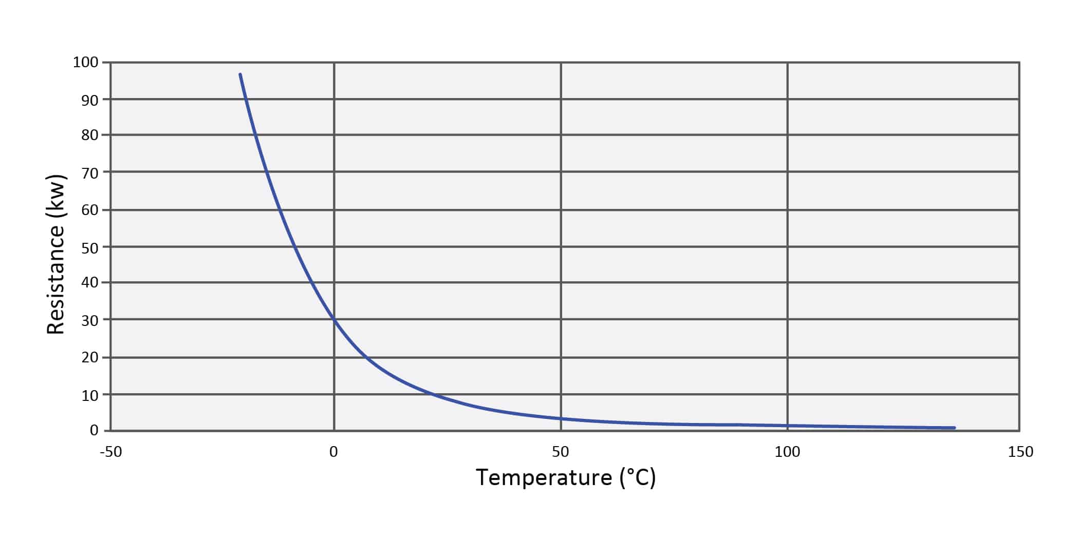
To determine if accuracy is needed it is important to first understand how the sensor is used in the application. Let us take as an example a temperature measurement based on an NTC (Negative Temperature Coefficient) thermistor. The first thing that draws attention in the graph of resistance versus temperature of the NTC is the non-linearity of the device, as can be seen in figure 2.

temperature versus resistance variations.
If the designer only needs to measure the NTC at a low ambient temperature, then an ADC with a lower resolution can be used. On the other hand, if you need to measure the temperature in the entire range, you must take into account the worst possible case when the ambient temperature is higher, you must use an ADC with a much higher resolution.
To equate it to the accuracy of the system, the temperature range must be defined and the temperature accuracy required for that range calculated. The temperature range would be converted to an analog voltage input range for the ADC, and the accuracy would be the smallest deviation from the measured analog input that the application could tolerate.
Precision
Now let's move on to precision. Ideally, precision should be better than accuracy. If a temperature reading is used in the feedback loop of a system, this loop should be very stable. If the precision is worse than the accuracy, the feedback loop could become unstable.
Measure the accuracy and precision of an ADC
The ADC specifications that influence accuracy the most are integral nonlinearity, differential nonlinearity, offset, offset drift, gain, and gain drift.
To determine the accuracy it is necessary to know the contributions of these sources of error. Similarly, precision is defined by the term ENOB (Effective Number of Bits), that is, the number of effective bits. Indicates the deviation for a set of ADC readings from the true mean. In other words, 68,3% (or one standard deviation from the mean) of the ADC readings will fall within the range defined by ENOB.
To illustrate, let's go back to the NTC example.
Let's say the NTC output is calibrated to be linear over the entire temperature range to provide 0V at -40°C and 2,5V at 85°C, and we want to measure to within 1°C. An accuracy of 1°C over a range of 125°C is equivalent to an accuracy of 0,8% over the entire range. Suppose we have a 12 bit ADC with a total error of 1 LSB and an input range of 2,5V, in which case the measurement accuracy of the ADC will be 1/4096, 0,024% or 2,5V/4096 bit. or 610uV/bit, which is 33 times better than the required accuracy. Therefore, theoretically, a 12-bit ADC should offer sufficient accuracy to meet these requirements.
Now let's take a closer look at the example of an integrated 12-bit 400 kSPS ADC built into a new microcontroller.
In its data sheet, the TUE (total unadjusted error), that is, the total unadjusted error, is ±1,8% between -40°C and 85°C. A 6-bit ADC with a total error of 1 LSB offers an accuracy of 1,6%. So what happens to the other 6 bits of the 12 bit ADC? Not only that, but the error can also be positive or negative, so there can be a 3,6% or 90 mV variance in the ADC readings. In this case, the high error of gain with respect to temperature contributes a lot to reduce the accuracy. This large error in accuracy comes as a result of the inherent limitations of the process technology. Care should be taken when reading the data sheets for onboard ADCs as in some cases for onboard ADCs they only indicate ADC performance when using an external voltage reference due to noise, drift and poor reference performance built-in voltage, which defeats the purpose of using built-in analog components. Therefore, the accuracy of the integrated ADC is not good enough in this case to meet our 0,8% requirement.
What about the precision of the integrated ADC then? If we consult the precision data, the ENOB is 11,1 bit, which is equivalent to a resolution of about 1,1 mV in the 2,5V analog input signal. Precision is about 80 times better than accuracy. The result is that the integrated ADC has an error of 90,7 mV and an accuracy of about 1,1 mV rms. The accuracy of the built-in ADC can be improved by using an external reference, but as the ADC has been specified it is unknown to what extent the external reference will improve accuracy.
Now let's evaluate a stand-alone ADC like Microchip Technology's MCP33141-10.
From the accuracy of this 12 bit 1 MSPS ADC we calculate the TUE and compare it with that of the integrated ADC. The TUE for the temperature range from -40°C to 125°C is equivalent to ±0,06%, that is, its accuracy is 30 times better than the integrated ADC and within a wider temperature range. As far as precision is concerned, the standalone ADC has an ENOB of 11,8 bit, so in this example the standalone ADC's precision is about 4 times better than its accuracy. The result is that the standalone ADC has an error of 2,9 mV and an accuracy of about 0,7 mV rms.

In this comparison, the accuracy is very similar between an integrated and a stand-alone ADC. However, while the built-in ADC was accurate it could not meet the 1% accuracy requirement. Only the standalone ADC was able to meet the accuracy requirement of 1°C or 0,8% of temperature for an NTC temperature sensor.
Observations on the accuracy and precision of the system
The problem with querying only the accuracy of the ADC is that it does not take into account the variables in the system or systems in which the ADC is used. If the ADC is accurate and precise, the ADC output will be consistent across all devices and under all conditions, and not on a given device or under given conditions.
Therefore, if accuracy or consistency are not needed between systems or for all conditions under which a system is to operate, the advantages of an integrated ADC will be less complexity, size, and price. The complexity will be less with an integrated ADC since there will be no need to develop software for connection to an external ADC and no need to consider the placement and routing of analog and digital signals to and from the ADC. The integration of the ADC into the microcontroller also decreases the overall footprint of the board. In addition, the price of a microcontroller with an integrated ADC is usually lower than the sum of the price of the microcontroller and a stand-alone ADC.
That being said, if you require precision, accuracy, and consistency between systems or for all system operating conditions, be very careful when choosing your ADC. The designer should not fall into the trap of believing that the variation between devices will be small and that digital compensation techniques can be used to compensate for inaccuracy or inconsistent analog performance. It should be remembered that digital compensation techniques can decrease system accuracy and increase complexity due to inherent process limitations.
It is also a good idea to check that the ADC specifications and voltage reference indicate not only accuracy but also accuracy vs. temperature. If this data is not available for the ADC, there is a high risk that process, manufacturing, test, and temperature variations will manifest as errors in the system. And even worse, these variations are not deterministic: one device may have significant positive gain drift and another may have significant negative gain drift. These large variations can cause instability in the system.
The decision between an integrated and a stand-alone ADC is based simply on cost, accuracy, and consistency of performance. Once accuracy or consistency of performance is established, selection can be easily made.


